200308025
Basic Operation (continued)
Battery Replacement
Rear Panel continued
Input Breaker: Protect your electrical circuit from overcurrent draw from the UPS load. If this breaker trips, remove some of the load, then reset it by pressing the breaker in.
External Battery Connector (Select Models Only): Use to connect Tripp Lite external battery packs for additional runtime. The specifi- cations section of this manual lists the Tripp Lite external battery packs that are compatible with your model. Refer to instructions
1 |
2 |
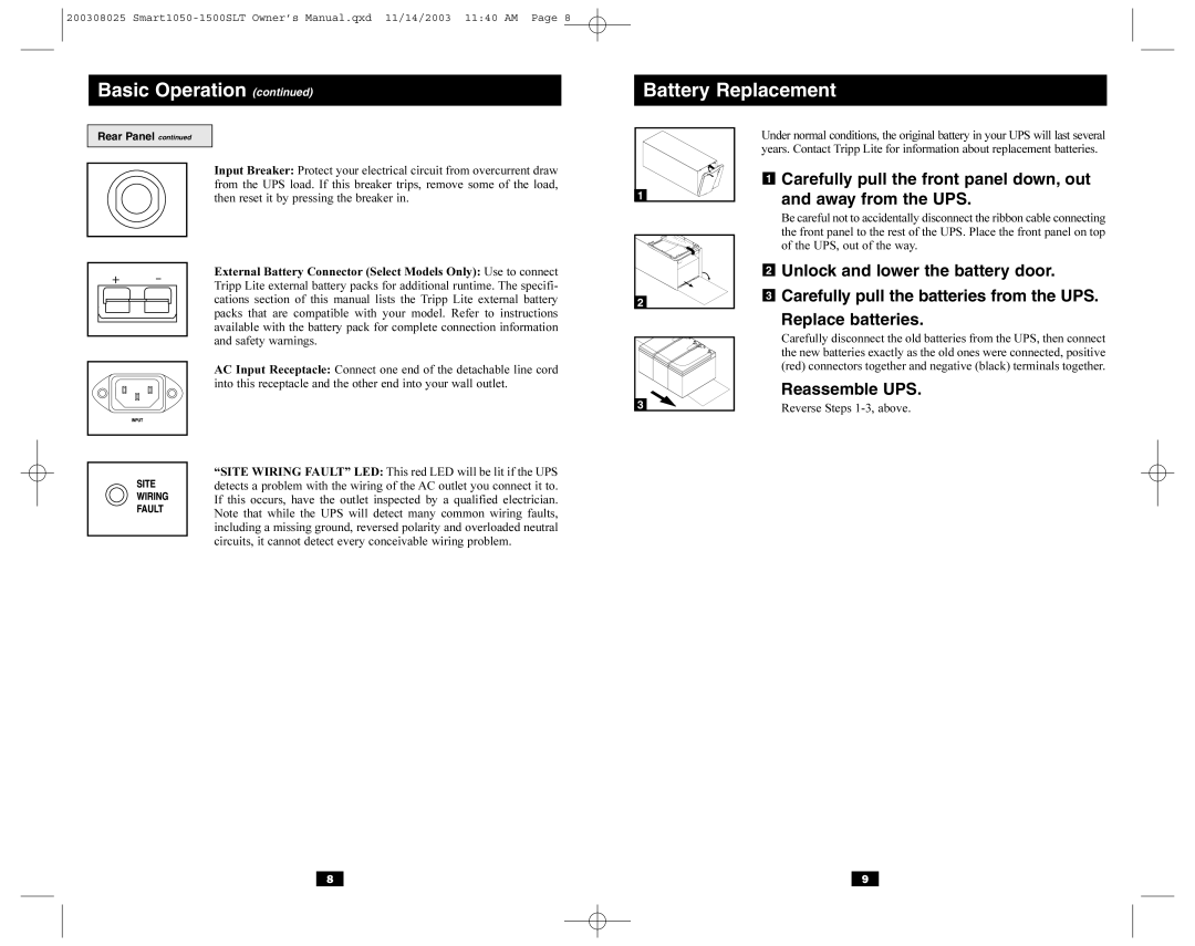
Under normal conditions, the original battery in your UPS will last several years. Contact Tripp Lite for information about replacement batteries.
1Carefully pull the front panel down, out
and away from the UPS.
Be careful not to accidentally disconnect the ribbon cable connecting the front panel to the rest of the UPS. Place the front panel on top of the UPS, out of the way.
2Unlock and lower the battery door.
3Carefully pull the batteries from the UPS.
available with the battery pack for complete connection information and safety warnings.
AC Input Receptacle: Connect one end of the detachable line cord into this receptacle and the other end into your wall outlet.
“SITE WIRING FAULT” LED: This red LED will be lit if the UPS detects a problem with the wiring of the AC outlet you connect it to. If this occurs, have the outlet inspected by a qualified electrician. Note that while the UPS will detect many common wiring faults, including a missing ground, reversed polarity and overloaded neutral circuits, it cannot detect every conceivable wiring problem.
3 |
Replace batteries.
Carefully disconnect the old batteries from the UPS, then connect the new batteries exactly as the old ones were connected, positive (red) connectors together and negative (black) terminals together.
Reassemble UPS.
Reverse Steps
8 |
| 9 |