Section
3Features and Controls
WARNING
Before operating your machine, carefully read and understand all safety, controls and operating instructions in this Manual, the separate Engine Owner’s Manual, and on the decals on the machine.
Failure to follow these instructions can result in serious personal injury.
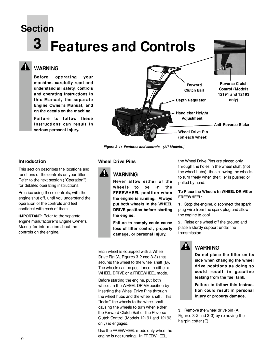
Forward
Clutch Bail
Depth Regulator
Handlebar Height
Adjustment
Wheel Drive Pin (on each wheel)
Reverse Clutch Control (Models 12191 and 12193 only)
Anti-Reverse Stake
Figure 3-1: Features and controls. (All Models.)
Introduction
This section describes the locations and functions of the controls on your tiller. Refer to the next section (“Operation”) for detailed operating instructions.
Practice using these controls, with the engine shut off, until you understand the operation of the controls and feel confident with each of them.
IMPORTANT: Refer to the separate engine manufacturer’s Engine Owner’s Manual for information about the controls on the engine.
10
Wheel Drive Pins
WARNING
Never allow either of the wheels to be in the FREEWHEEL position when the engine is running. Always put both wheels in the WHEEL DRIVE position before starting the engine.
Failure to comply could cause loss of tiller control, property damage, or personal injury.
Each wheel is equipped with a Wheel Drive Pin (A, Figures
Before starting the engine, put both wheels in the WHEEL DRIVE position by inserting the Wheel Drive Pins through the wheel hubs and the wheel shaft. This “locks” the wheels to the wheel shaft, causing the wheels to turn when either the Forward Clutch Bail or the Reverse Clutch Control (Models 12191 and 12193 only) is engaged.
Use the FREEWHEEL mode only when the engine is not running. In FREEWHEEL,
the Wheel Drive Pins are placed only through the holes in the wheel shaft (not the wheel hubs), thus allowing the wheels to turn freely when the tiller is pushed or pulled by hand.
To Place the Wheels in WHEEL DRIVE or
FREEWHEEL:
1.Stop the engine, disconnect the spark plug wire from the spark plug and allow the engine to cool.
2.Raise one wheel off the ground and place a sturdy support under the transmission.
WARNING
Do not place the tiller on its side when changing the wheel drive positions as doing so could result in gasoline leaking from the fuel tank.
Failure to follow this instruc- tion could result in personal injury or property damage.
3.Remove the wheel drive pin (A, Figures