Section 3: Features and Controls
Reverse Clutch
The Reverse Clutch (C, Figure
WARNING
•Use extreme caution when reversing or pulling the machine towards you. Look behind to avoid obstacles.
•Never attempt to till in reverse.
Failure to follow this warning could result in personal injury or property damage.
To Operate the Reverse Clutch:
1.Put the Wheel Gear Lever in the ENGAGE position (see the “WARNING” statement on previous page).
2.Stop all tiller motion by releasing the Forward Clutch levers.
3.Lift up the handlebars until the tines clear the ground, look behind you to avoid any obstacles, and then pull the Reverse Clutch control knob out. The tines and wheels will rotate in a reverse direction.
4.Release the Reverse Clutch control knob to disengage (stop) the wheels and tines. All reverse motion will stop (the engine will continue to run).
Depth Regulator
This lever (D, Figure
The highest notch (lever all the way down) raises the tines approximately
Moving the lever up increases the tilling depth. The lowest notch allows a tilling depth of approximately six to eight inches, depending on soil conditions.
For best results, always begin tilling at a very shallow depth setting and gradu- ally increase the tilling depth. Complete details on using the Depth Regulator are found in the “Operation” Section of this manual.
WARNING
•Do not attempt to till too deeply too quickly. Gradually work down to deeper tilling depths.
•Place the Depth Regulator Lever in the “travel” position before starting the engine. This position prevents the tines from touching the ground until you are ready to begin tilling.
Failure to follow this warning could result in personal injury or property damage.
D
Figure 3-2: Depth Regulator Lever.
Handlebar Height Adjustment
The handlebar height is adjustable to four different settings. Set the handlebar height to a comfortable setting, but keep in mind that the handlebars will be lower when the tines are engaged in the soil.
WARNING
Whenever the handlebar height is changed, the Forward Clutch shift mech- anism must be readjusted.
When adjusting or checking the Forward Clutch mechanism, shut engine off, dis- connect spark plug wire and prevent it from touching the spark plug.
Failure to follow this warning could allow the Forward Clutch mechanism to operate improperly which could result in personal injury or property damage.
To Adjust the Handlebar Height:
1.Stop the engine, wait for all parts to stop moving and then disconnect the spark plug wire. Remove the ignition key on electric start models.
2.Loosen the two screws at the lower ends of the handlebar.
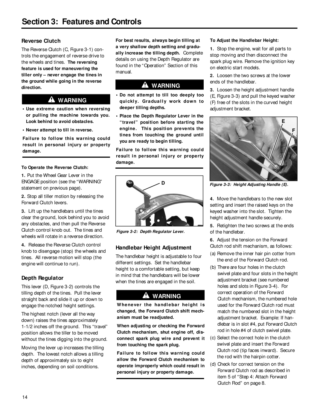
3.Loosen the height adjustment handle (E, Figure
(F) free of the slots in the curved height adjustment bracket.
E
F
Figure 3-3: Height Adjusting Handle (E).
4.Move the handlebars to the new slot setting and insert the raised keys on the keyed washer into the slot. Tighten the height adjustment handle securely.
5.Retighten the two screws at the ends of the handlebar.
6.Adjust the tension on the Forward Clutch rod shift mechanism, as follows:
(a)Remove the inner hair pin cotter from the end of the Forward Clutch rod.
(b)There are four holes in the clutch swivel plate and four slots in the height adjustment bracket (see numbered holes and slots in Figure
(c)Select the correct hole in the clutch swivel plate and insert the Forward Clutch rod (tip faces inward). Secure the rod with the hairpin cotter.
(d)Check for correct tension on the Forward Clutch rod as described in item 5 of “Step 4: Attach Forward Clutch Rod” on page 8.
14