Section 5: Maintenance
WARNING Before inspecting, cleaning or servicing the unit, shut off engine, wait for all parts to come to a complete stop, disconnect spark plug wire and move wire away from spark plug. Remove ignition key on elec- tric start models. Failure to follow these instructions can result in serious personal injury or property damage.
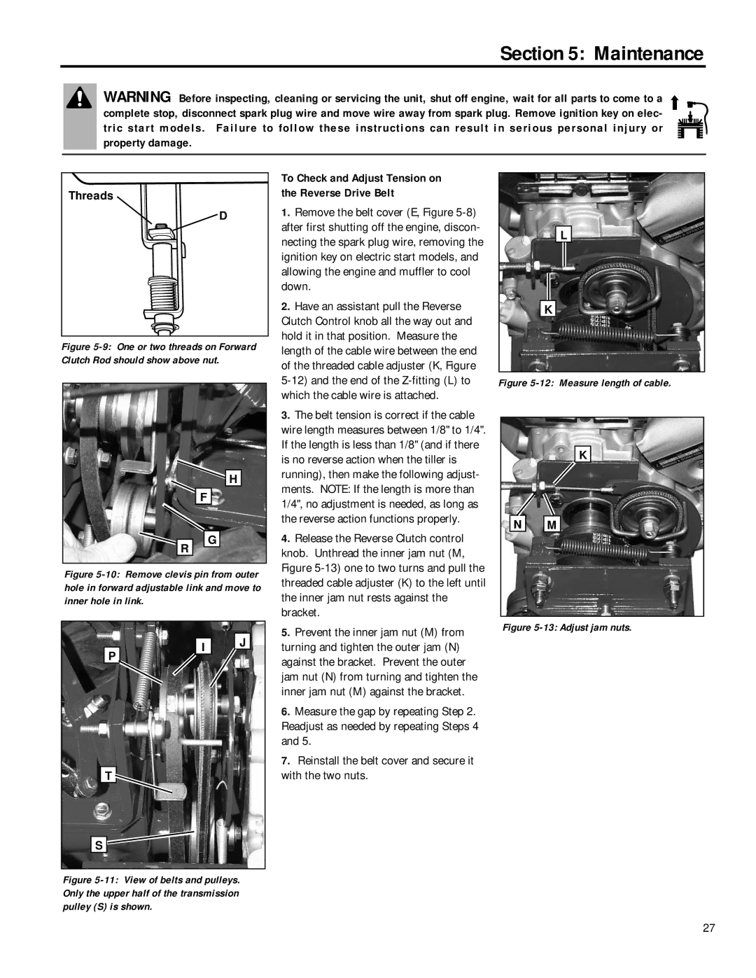
Threads
D
Figure 5-9: One or two threads on Forward Clutch Rod should show above nut.
H
F
To Check and Adjust Tension on the Reverse Drive Belt
1. Remove the belt cover (E, Figure |
after first shutting off the engine, discon- |
necting the spark plug wire, removing the |
ignition key on electric start models, and |
allowing the engine and muffler to cool |
down. |
2. Have an assistant pull the Reverse |
Clutch Control knob all the way out and |
hold it in that position. Measure the |
length of the cable wire between the end |
of the threaded cable adjuster (K, Figure |
which the cable wire is attached. |
3. The belt tension is correct if the cable |
wire length measures between 1/8" to 1/4". |
If the length is less than 1/8" (and if there |
is no reverse action when the tiller is |
running), then make the following adjust- |
ments. NOTE: If the length is more than |
1/4", no adjustment is needed, as long as |
the reverse action functions properly. |
L
K
Figure 5-12: Measure length of cable.
K
N ![]()
![]() M
M
R
G
4. Release the Reverse Clutch control |
knob. Unthread the inner jam nut (M, |
Figure |
Figure 5-10: Remove clevis pin from outer hole in forward adjustable link and move to inner hole in link.
P | I | J |
| ||
|
| |
T |
|
|
S |
|
|
Figure 5-11: View of belts and pulleys. Only the upper half of the transmission pulley (S) is shown.
threaded cable adjuster (K) to the left until |
the inner jam nut rests against the |
bracket. |
5. Prevent the inner jam nut (M) from |
turning and tighten the outer jam (N) |
against the bracket. Prevent the outer |
jam nut (N) from turning and tighten the |
inner jam nut (M) against the bracket. |
6. Measure the gap by repeating Step 2. |
Readjust as needed by repeating Steps 4 |
and 5. |
7. Reinstall the belt cover and secure it |
with the two nuts. |
Figure 5-13: Adjust jam nuts.
27