5210R specifications
The Troy-Bilt 5210R is a versatile and durable snow blower designed for homeowners who seek efficient snow removal solutions. With its powerful features and advanced technologies, the 5210R stands out in the competitive landscape of outdoor equipment.At the heart of the Troy-Bilt 5210R is its robust 208cc engine, which delivers reliable performance when tackling both light and heavy snowfall. The engine is engineered for easy start-ups, ensuring you can quickly get to work even in cold weather conditions. The machine's 24-inch wide clearing width allows you to efficiently clear large areas, while its 21-inch intake height enables it to handle deep snow with ease.
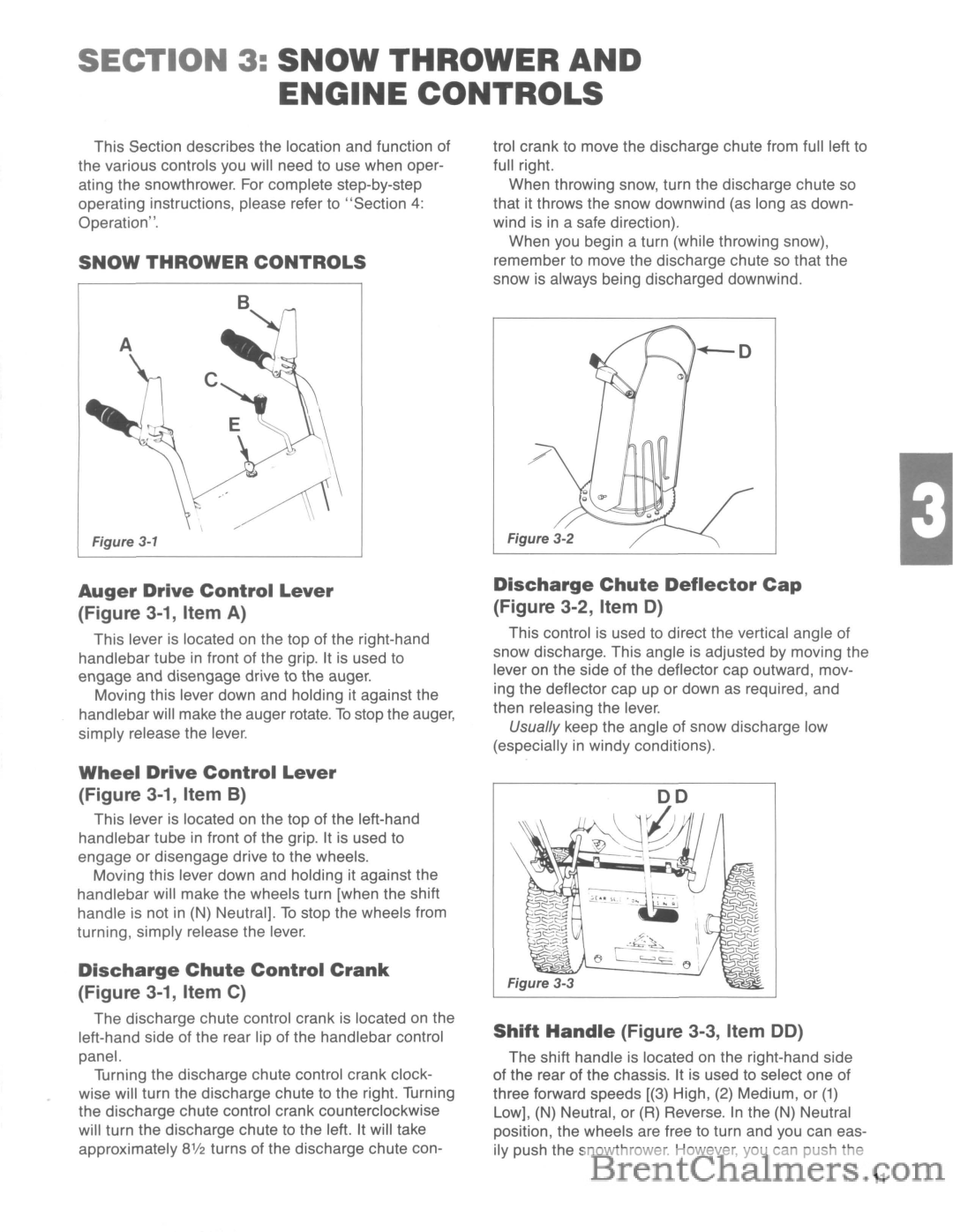
One of the standout features of the Troy-Bilt 5210R is its In-Dash Headlight. This essential addition enhances visibility during early morning or evening snow removal tasks, making it a safer and more user-friendly option. The control panel is designed with ergonomics in mind, featuring easy-to-reach levers and controls that allow users to adjust speed and chute direction with minimal effort.
The 5210R boasts an innovative 180-degree adjustable chute, which allows for precise snow placement. This feature is especially useful for directing snow away from walkways or driveways and keeping your property clear and safe. Additionally, the chute is made from durable materials, ensuring it can withstand the rigors of harsh winter conditions.
The snow blower's heavy-duty tires provide excellent traction and stability on various terrains, allowing users to navigate through snow-covered surfaces easily. Troy-Bilt's signature power steering feature further enhances maneuverability, making it simple to turn and control the machine even in tight spaces.
For added convenience, the Troy-Bilt 5210R features an easy-to-clean design that simplifies maintenance. The accessible parts allow for quick inspections and cleaning, ensuring the machine remains in peak condition season after season.
In conclusion, the Troy-Bilt 5210R snow blower is a powerful, reliable, and user-friendly tool for tackling winter weather challenges. With its robust engine, adjustable chute, and user-oriented design, it provides homeowners with an effective solution for maintaining clear driveways and walkways during snowy months. This makes the 5210R an excellent investment for anyone looking to enhance their snow removal arsenal.

