SECTION2: ASSEMBLY
WARNING: To prevent personal injury or property damage,do not start the engine until all assemblysteps are complete andyou have read and understandthe safety and operating instructions in this manual.
INTRODUCTION
Carefullyfollow these assemblysteps to correctly prepareyour tiller for use. It _s recommended that you readthis Section in its entirety before beginning assembly.
NOTE: Various tiller models are presented in this Manual. Use only the information appropriate for your tiller model,
INSPECTUNIT
Inspectthe unit and carton for damage tm- mediately after delivery. Contactthe carri- er (trucking company) if you find or suspectdamage. Inform them of the dam- ageand request instructions for filing a claim. To protect your rights, put your claim in writing and mail a copyto the car- rier within 15 days after the unit has been
delivered. Contact
TOOLSMATERIALSNEEDED
(11
(2)
(1)Largead Jstable wrench _Models634F/634Bonly)
(.11 Scissors totrim plastic ties
(1) Ruler (for belt tension check_
Ill Block of wood (to support tiller when removing wheels)
(1)Tire pressure gauge _for modelswith pneumatic tires_
111 Cleanoil funnel
Ill Motor oil Referto the EngineOwner's Manualfor oil specificationsand quantityrequired.
* Adlustable wrenches may Deused.
ASSEMBLYSTEPS
STEP 1: UNPACKING INSTRUCTIONS
NOTE: While unpackin0, do not severely bendany control cables.
1.Thetiller weighs approximately133 lbs. Do not attempt to remove it from the ship- ping platform until instructed to do so in these Assembly steps.
2.Removeany packaging materialfrom the carton. Removeany staples from the bottom of the carton and removethe car- ton from the shipping platform.
3.Removeall unassembled partsand the separatehardware bagfrom the carton. Checkthat you havethe items listed in the LoosePartsList(contactyourlocaldealer orthe factory items are missing or dam- aged).
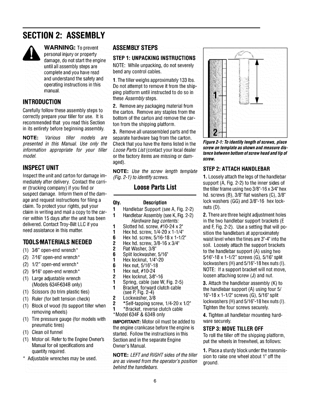
NOTE: Use the screw length template (Fig.
LoosePartsList
Qty.Description
1HandlebarSupport (seeA, Fig.
1HandlebarAssembly(see K,
1Slotted hd. screw
1Hex bd. screw
6Hex hd. screw
2Hex hd. screw.
2FlatWasher.3/8°
6Split Iockwashe_ 5/16_
1Hex Iocknut.
8Hex nut.
1Hex nut
2Hex Iocknut.
1Spring, cable (see W, Fig.
1Bracket. forward clutch cable (see P, Fig.
2Lockwasher 3/8
2
1*Bracket reverseclutch cable Model 634F & 634B only
IMPORTANT: Motor oil must beaddedto the enginecrankcasebefore the engine is started. Followthe instructions inthis Sectionand in the separateEngine Owner'sManual.
NOTE:LEFTandRIGHTsidesofthetiller
are as viewed from the operator's position behind the handlebars.
m
Figure2-1: Toidentify lengthofscrews,place screwon templateasshownandmeasuredis- tancebetweenbottomofscrewheadandtipof
screw,
STEP 2: ATTACH HANDLEBAR
1.Looselyattach the legs of the handlebar support (A, Fig.
2.Therearethree height adjustment holes in the two handlebarsupport brackets (.E and E Fig.
3.Attach the handlebarassembty (.K_to the handlebarsupporl (A) using four 5.
4.Tighten all handlebarmounting hard- ware securely.
STEP 3: MOVE TILLER OFF
To roll the tiller off the shipping platform. put the wheels in freewhee as follows:
1.Placea sturdy block underthe transmis- sion to raise one wheelabout 1" off the
ground.