Connecting Floppy Drives
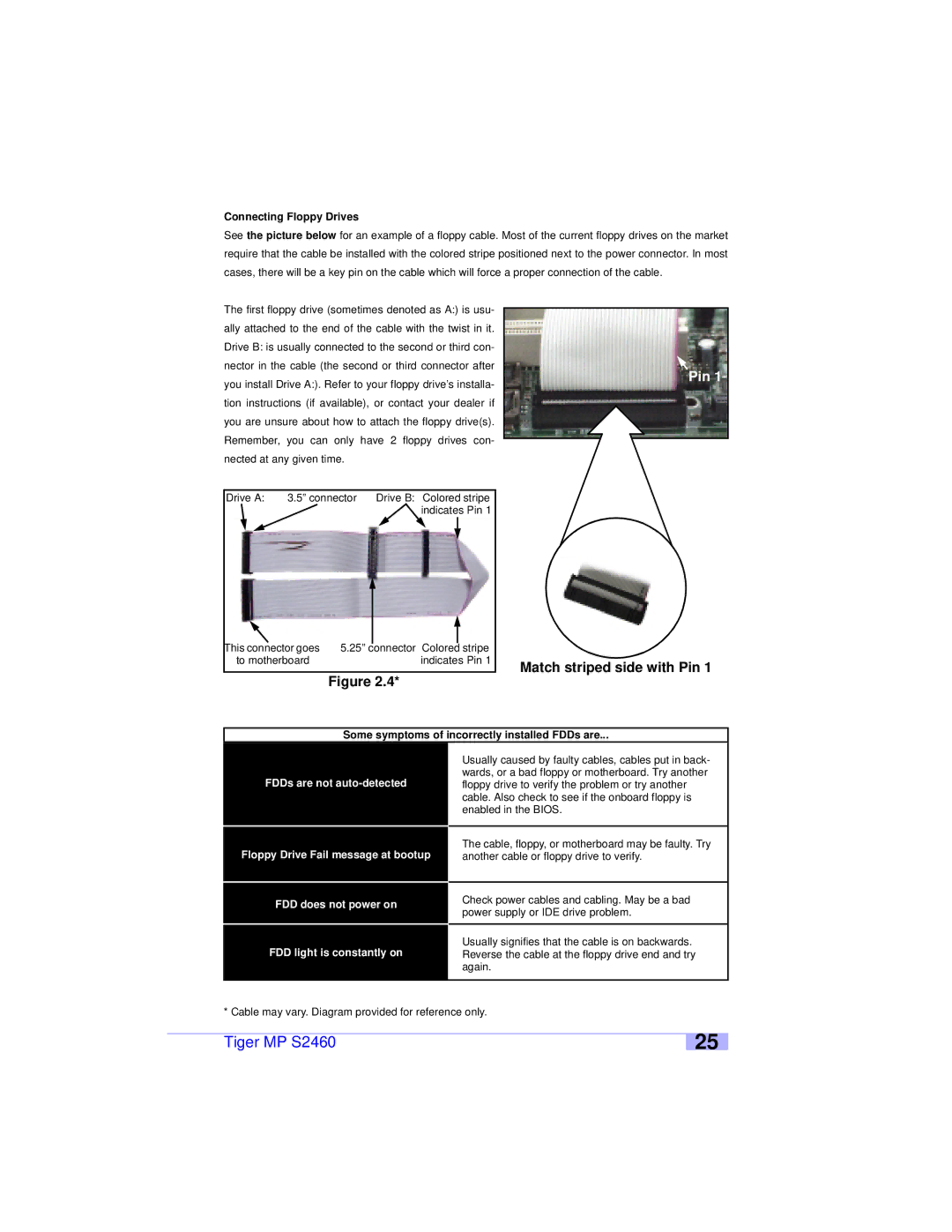
See the picture below for an example of a floppy cable. Most of the current floppy drives on the market require that the cable be installed with the colored stripe positioned next to the power connector. In most cases, there will be a key pin on the cable which will force a proper connection of the cable.
The first floppy drive (sometimes denoted as A:) is usu- ally attached to the end of the cable with the twist in it. Drive B: is usually connected to the second or third con- nector in the cable (the second or third connector after you install Drive A:). Refer to your floppy drive’s installa- tion instructions (if available), or contact your dealer if you are unsure about how to attach the floppy drive(s). Remember, you can only have 2 floppy drives con- nected at any given time.
Drive A: | 3.5” connector | Drive B: Colored stripe |
|
| indicates Pin 1 |
This connector goes | 5.25” |
| connector Colored |
| stripe |
|
| ||||
|
| ||||
to motherboard |
|
| indicates Pin 1 | ||
Figure 2.4*
Pin 1
Match striped side with Pin 1
Some symptoms of incorrectly installed FDDs are...
Usually caused by faulty cables, cables put in back- wards, or a bad floppy or motherboard. Try another
FDDs are not
Floppy Drive Fail message at bootup | The cable, floppy, or motherboard may be faulty. Try |
another cable or floppy drive to verify. |
FDD does not power on
FDD light is constantly on
Check power cables and cabling. May be a bad power supply or IDE drive problem.
Usually signifies that the cable is on backwards. Reverse the cable at the floppy drive end and try again.
* Cable may vary. Diagram provided for reference only.
Tiger MP S2460
25
