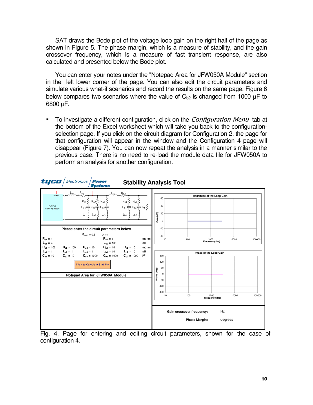
SAT draws the Bode plot of the voltage loop gain on the right half of the page as shown in Figure 5. The phase margin, which is a measure of stability, and the gain crossover frequency, which is a measure of fast transient response, are also calculated and presented below the Bode plot.
You can enter your notes under the "Notepad Area for JFW050A Module" section in the left lower corner of the page. You can also edit the circuit parameters and simulate various
To investigate a different configuration, click on the Configuration Menu tab at the bottom of the Excel worksheet which will take you back to the configuration- selection page. If you click on the circuit diagram for Configuration 2, the page for that configuration will appear in the window and the Configuration 4 page will disappear (Figure 7). You can now repeat the analysis in a manner similar to the previous case. There is no need to
Stability Analysis Tool
| SENSE | LS1 | RS1 |
|
| LS2 | RS2 |
|
|
|
|
|
|
|
|
|
|
| |
|
|
| Ra 1 | Ra2 | Ra3 |
| Rb1 | Rb2 |
|
| DC /DC |
| Ca 1 | Ca2 | Ca3 |
| Cb1 | C b2 | RL |
C ONVERTER |
|
| |||||||
|
|
|
|
|
|
|
| ||
|
|
| La1 | La2 | La3 |
| Lb1 | Lb2 |
|
|
| Please enter the circuit parameters below |
|
| |||||
|
|
| Rload = 0.5 | ohm |
|
|
|
| |
Rs1 | = 1 |
|
|
| Rs2 | = 5 |
|
| mohm |
Ls1 | = 4 |
|
|
| Ls2 | = 100 |
|
| nH |
Ra1 | = 100 | Ra2 = 100 | Ra3 = 10 | Rb1 | = 10 | Rb2 = 10 | mohm | ||
La1 | = 1 | La2 = 1 | La3 = 1 | Lb1 | = 10 | Lb2 = 10 | nH | ||
Ca1 | = 10 | Ca2 = 10 | Ca3 = 1000 | Cb1 | = 1000 | Cb2 = 1000 | ∝F | ||
|
|
| Click to Calculate Stability |
|
|
|
| ||
|
| Notepad Area for JFW050A Module |
|
| |||||
Magnitude of the Loop Gain
| 60 |
| 40 |
Gain (dB) | 20 |
0 | |
| |
|
10 | 100 | 1000 | 10000 | 100000 |
|
| Frequency (Hz) |
|
|
Phase of the Loop Gain
| 180 | |
| 120 | |
(deg) | 60 | |
0 | ||
Phase | ||
| ||
|
10 | 100 | 1000 | 10000 | 100000 |
|
| Frequency (Hz) |
|
|
Gain crossover frequency: | Hz |
Phase Margin: | degrees |
Fig. 4. Page for entering and editing circuit parameters, shown for the case of configuration 4.
10