Tyco Electronics PL0349 manual Product Models, Installation, Copper and Fiber Cabling Guidelines

Models: PL0349

1 12
Download 12 pages 8.75 Kb
Page 4
Image 4

8 Port Ethernet Smart Switch With Fibre Uplink

Product Models

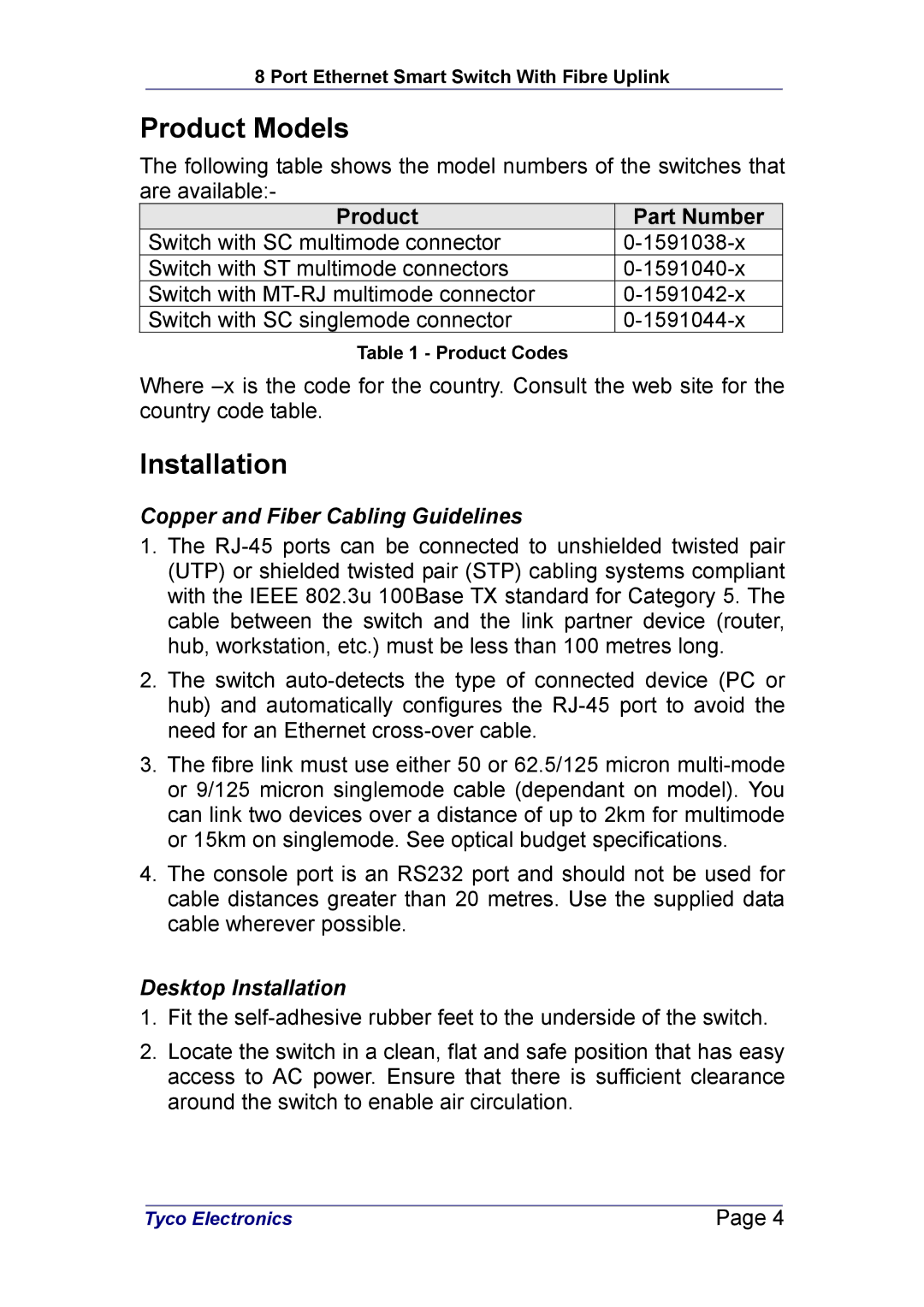
The following table shows the model numbers of the switches that are available:-

Product

Part Number

Switch with SC multimode connector

0-1591038-x

Switch with ST multimode connectors

0-1591040-x

Switch with MT-RJ multimode connector

0-1591042-x

Switch with SC singlemode connector

0-1591044-x

Table 1 - Product Codes

Where –x is the code for the country. Consult the web site for the country code table.

Installation

Copper and Fiber Cabling Guidelines

1.The RJ-45 ports can be connected to unshielded twisted pair (UTP) or shielded twisted pair (STP) cabling systems compliant with the IEEE 802.3u 100Base TX standard for Category 5. The cable between the switch and the link partner device (router, hub, workstation, etc.) must be less than 100 metres long.

2.The switch auto-detects the type of connected device (PC or hub) and automatically configures the RJ-45 port to avoid the need for an Ethernet cross-over cable.

3.The fibre link must use either 50 or 62.5/125 micron multi-mode or 9/125 micron singlemode cable (dependant on model). You can link two devices over a distance of up to 2km for multimode or 15km on singlemode. See optical budget specifications.

4.The console port is an RS232 port and should not be used for cable distances greater than 20 metres. Use the supplied data cable wherever possible.

Desktop Installation

1.Fit the self-adhesive rubber feet to the underside of the switch.

2.Locate the switch in a clean, flat and safe position that has easy access to AC power. Ensure that there is sufficient clearance around the switch to enable air circulation.


Tyco Electronics

Page 4


Page 4
Image 4
Tyco Electronics PL0349 manual Product Models, Copper and Fiber Cabling Guidelines, Desktop Installation