NOTE
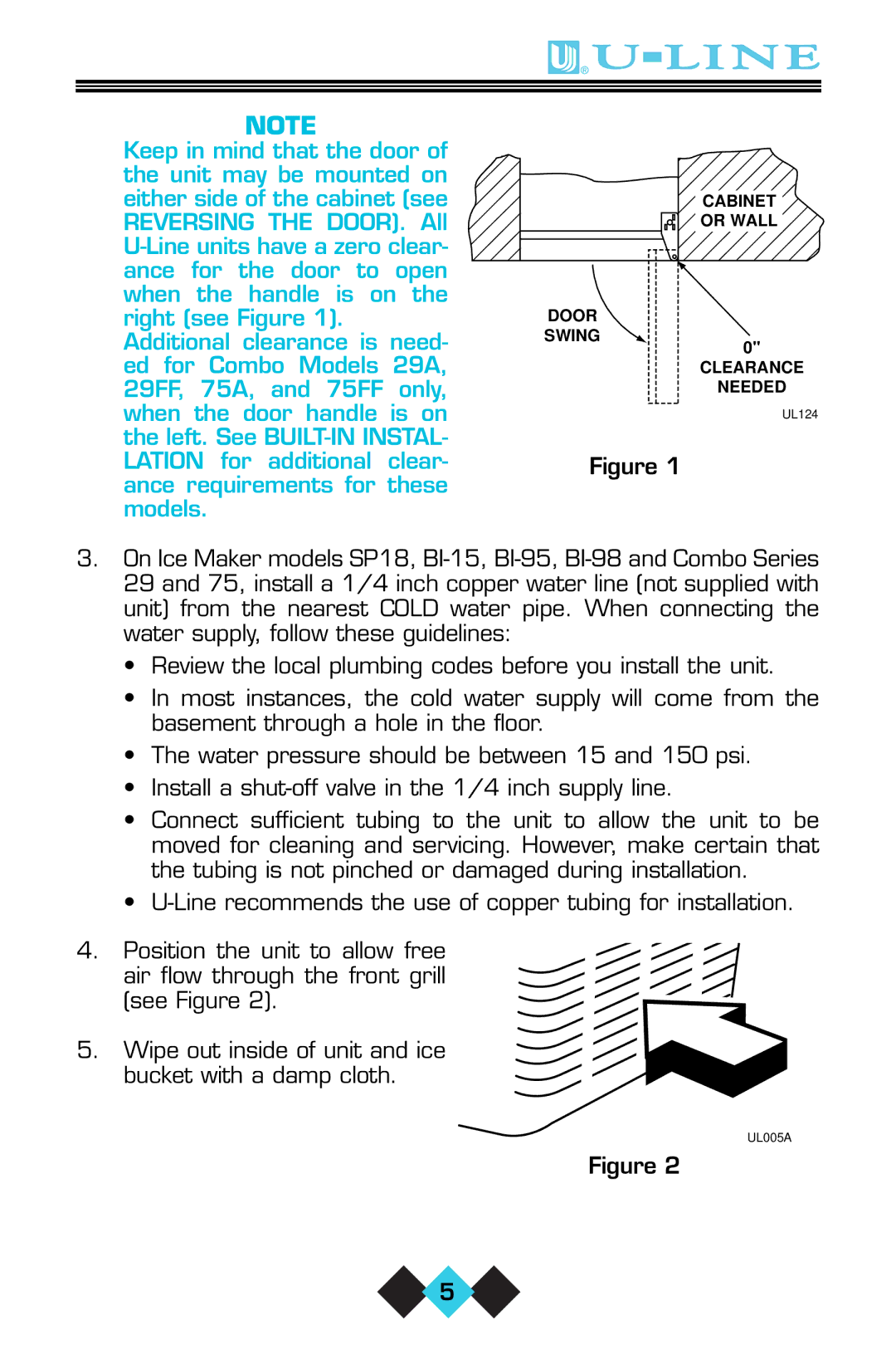
Keep in mind that the door of the unit may be mounted on either side of the cabinet (see REVERSING THE DOOR). All
Additional clearance is need- ed for Combo Models 29A, 29FF, 75A, and 75FF only, when the door handle is on the left. See
CABINET
OR WALL
DOOR
SWING
0"
CLEARANCE
NEEDED
UL124
Figure 1
3.On Ice Maker models SP18,
•Review the local plumbing codes before you install the unit.
•In most instances, the cold water supply will come from the basement through a hole in the floor.
•The water pressure should be between 15 and 150 psi.
•Install a
•Connect sufficient tubing to the unit to allow the unit to be moved for cleaning and servicing. However, make certain that the tubing is not pinched or damaged during installation.
•
4.Position the unit to allow free air flow through the front grill
(see Figure 2).
5. Wipe out inside of unit and ice
bucket with a damp cloth.
UL005A
Figure 2
![]() 5
5 ![]()
