The default
factory setting
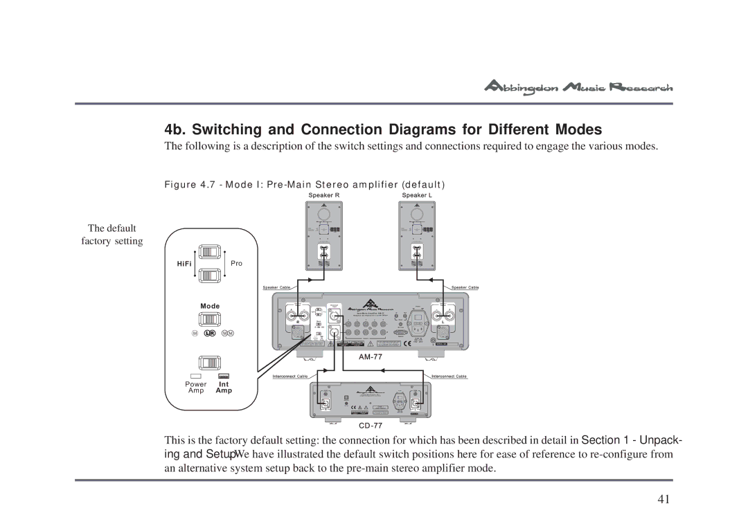
4b. Switching and Connection Diagrams for Different Modes
The following is a description of the switch settings and connections required to engage the various modes.
Figure 4.7 - Mode I: Pre-Main Stereo amplifier (default)
Speaker R | Speaker L |
HiFi |
| Pro |
| Mode |
|
M | L R | M M |
Power | Int |
Amp | Amp |
Speaker Cable |
|
|
|
| Speaker |
|
|
| Output |
|
|
+ |
| _ |
|
|
| HiFi | Pro |
| R | Mode | |
|
| Power | Int |
|
| Amp | Amp |
Under normal operation, set all switches to | |
the | default(bold) position. Please refer to |
the | instruction manual for further details. |
Interconnect Cable
Balanced |
|
| Power |
Input |
|
| |
|
| On | Off |
Dual Mono Amplifier AM 77 | In | Out |
|
| Designed and Engineered in Great Britain |
|
|
| |||
1 | 2 | 3 | 4 | 5 | Sync |
|
|
|
|
|
| L |
|
|
|
|
|
|
| IR Link |
|
| |
|
|
|
| R |
|
|
|
|
|
|
|
| Option |
|
|
|
| Inputs |
|
|
| ~ AC IN | |
|
|
|
|
|
| 90V | 135V |
CAUTION | ATTENTION |
|
| User Serviceable Components Inside. | 190V | 260V | |
| ! | No For service,contact your Authorised |
| ||||
RISK OF ELECTRIC SHOCK | RISQUE DE CHOC ELECTRIQUE |
| Dealer or Distributor.Any modifications to |
|
| ||
DO NOT OPEN | NE PAS OUVRIR |
| this equipment will void all warranties. |
|
| ||
|
|
|
| ||||
Compact Disk Processor CD 77
Speaker Cable
Speaker |
|
Output |
|
_ | + |
L |
|
SERIAL NO. |
|
Interconnect Cable
! | CLASS 1 |
LASER PRODUCT | |
R | L |
CAUTION ATTENTION |
|
CD
This is the factory default setting: the connection for which has been described in detail in Section 1 - Unpack- ing and Setup. We have illustrated the default switch positions here for ease of reference to
41