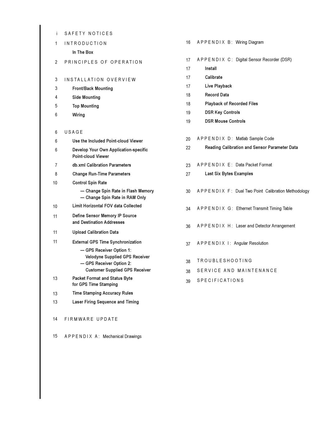
HDL-64E S2, HDL-64E S2.1 specifications
The Velodyne Acoustics HDL-64E S2.1 and HDL-64E S2 represent cutting-edge advancements in Lidar technology, specifically designed for autonomous vehicle navigation and mapping applications. These high-definition lidar sensors are acclaimed for their precision, reliability, and robustness, making them indispensable tools in various industries, from robotics to transportation.One of the defining features of the HDL-64E series is its 64 laser channels, which allow for high-resolution 3D mapping of the environment. This multi-channel design significantly improves the sensor's ability to capture fine details in the surrounding area, providing a complete spatial representation necessary for autonomous driving. The HDL-64E S2.1 and S2 can generate dense point clouds with over 1.3 million points per second, facilitating real-time data acquisition and processing capabilities.
The HDL-64E series employs advanced technologies for optimal performance. Its 360-degree horizontal field of view and a vertical field of view ranging from -15 to +15 degrees allow the sensors to detect and classify objects in a comprehensive manner. This feature is crucial for ensuring the safety and efficacy of autonomous vehicles, as it enables them to perceive their surroundings from multiple angles.
In terms of accuracy, the HDL-64E models boast a measurement range of up to 120 meters, with an accuracy of ±2 centimeters. This level of precision ensures that autonomous systems can make informed decisions based on reliable data, essential for avoiding obstacles and navigating complex environments.
The sensors are designed to operate effectively in a range of environmental conditions. With IP67-rated waterproofing and robustness against dust and debris, the HDL-64E S2.1 and S2 are built to withstand challenging operating environments, thus ensuring continuous, dependable performance.
Integration of the HDL-64E series into existing systems is streamlined, thanks to its advanced Ethernet interface. This functionality makes it easier for developers to incorporate the Lidar data into existing software frameworks, enhancing the usability of the sensor in various applications.
In summary, the Velodyne Acoustics HDL-64E S2.1 and HDL-64E S2 represent a significant leap forward in Lidar technology, featuring high-resolution mapping, advanced detection capabilities, and rugged design. These characteristics make them an ideal choice for companies looking to implement reliable and precise sensing solutions in their autonomous systems.
