1990 specifications
Vermont Casting, founded in 1975, is renowned for its commitment to crafting high-quality cast iron wood stoves and heaters that merge efficiency with timeless design. By 1990, Vermont Casting had established itself as a leader in the industry, celebrated for its innovative approach to heating solutions and commitment to sustainability.The 1990 models reflected an impressive evolution in technology and aesthetics. One of the standout features of Vermont Casting stoves was their utilization of advanced air control systems. This technology allowed users to regulate the burn speed and heat output effectively, making it easier to maintain consistent warmth in the home while optimizing fuel efficiency. The stoves featured an adjustable air inlet that provided users with the power to control combustion according to their needs.
In terms of design, Vermont Casting stoves were characterized by their iconic, rustic appearance, often featuring a choice of colors and finishes that allowed them to blend seamlessly into a variety of home aesthetics. The deep, rich finishes of the cast iron, coupled with elegant detailing, made each unit not only a heating appliance but also a centerpiece in living spaces. This commitment to aesthetics extended to the variety of designs available, including both traditional and modern styles, catering to diverse consumer preferences.
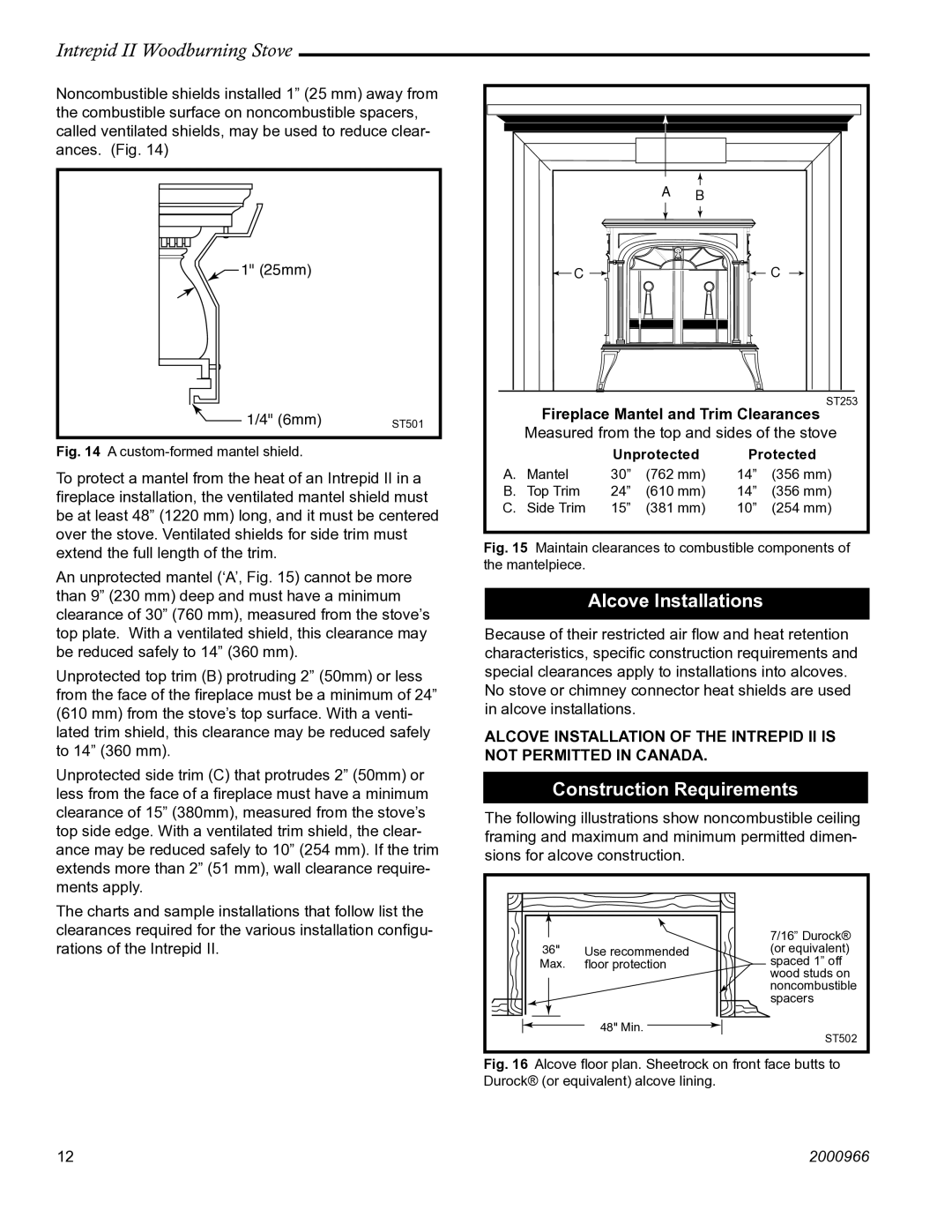
Vermont Casting also prioritized safety in their 1990 models. Many stoves were equipped with features such as double doors with glass panels, allowing users to enjoy the beauty of the flames while minimizing the risk of accidental burns. Some models incorporated heat shields that protected surrounding walls and furniture from excessive heat, further enhancing safety at home.
Durability was another hallmark of Vermont Casting’s reputation. The use of high-quality cast iron meant that these stoves were built to withstand years of use, often becoming familial heirlooms passed down through generations. In addition to resilience, cast iron was known for its ability to retain heat even after the fire had gone out, providing lingering warmth long into the night.
Overall, Vermont Casting in 1990 represented a harmonious blend of timeless design, advanced functionality, and a commitment to sustainability. Their stoves were not merely heating appliances but symbols of a lifestyle choice that emphasized quality, elegance, and environmental responsibility, making them a preferred choice for homeowners seeking both reliability and beauty in home heating solutions.

