LDVT Series Direct Vent Gas Fireplace

Step 4

Install the 4” (102 mm) flex vent pipe to the appliance collar as described on Page 11. Secure the end with the first spring 6³⁄” (172 mm) from the flex pipe end to the unit.

Step 5

Slide the 7” (178 mm) flex vent pipe over the 4” flex vent pipe and secure the 7” collar as described on Page 11.

Step 6

Bend the flex pipe horizontal so the bottom of the horizontal pipe measure 6¹⁄” (165mm) from the top of the unit immediately after the 90° formation. (Fig. 25) Be sure to follow the 1” (25mm) rise in a 24” (610mm) horizontal run rule.

Step 7

Install the 4” flex then 7” flex to the termination.

1.Establish vent hole through the wall. (Fig. 18)

2.Remove soil to a depth of approximately 16” (406

mm)below base of snorkel. Install drain pipe. Install window well (not supplied). Refill hole with 12” (305

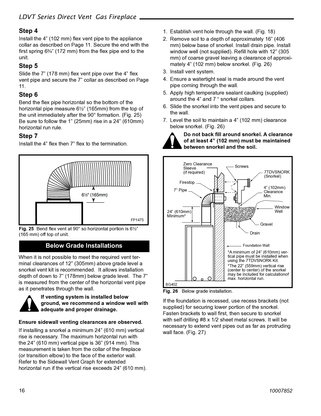
mm)of coarse gravel leaving a clearance of approxi- mately 4” (102 mm) below snorkel. (Fig. 26)

3.Install vent system.

4.Ensure a watertight seal is made around the vent pipe coming through the wall.

5.Apply high temperature sealant caulking (supplied) around the 4” and 7 “ snorkel collars.

6.Slide the snorkel into the vent pipes and secure to the wall.

7.Level the soil to maintain a 4” (102 mm) clearance below snorkel. (Fig. 26)

Do not back fill around snorkel. A clearance of at least 4” (102 mm) must be maintained between snorkel and the soil.

6���" (165mm)

FP1475

Fig. 25 Bend flex vent at 90° so horizontal portion is 6¹⁄₂” (165 mm) off top of unit.

Below Grade Installations

When it is not possible to meet the required vent ter- minal clearances of 12” (305mm) above grade level a snorkel vent kit is recommended. It allows installation depth of down to 7” (178mm) below grade level. The 7” is measured from the center of the horizontal vent pipe

Zero Clearance Sleeve (if required)

Firestop

7” Pipe

24” (610mm) Minimum*

Screws

7TDVSNORK

(Snorkel)

4” (102mm) Clearance Min.

Window

Well

Gravel

Drain

Foundation Wall

*A minimum of 24” (610mm) ver- tical pipe must be installed when using the 7TDVSNORK Kit.

*The 22” (559mm) vertical rise (center to center) of the snorkel may be included for calculationof max. horizontal run.

as it penetrates through the wall.

If venting system is installed below ground, we recommend a window well with adequate and proper drainage.

Ensure sidewall venting clearances are observed.

If installing a snorkel a minimum 24” (610 mm) vertical rise is necessary. The maximum horizontal run with the 24” (610 mm) vertical pipe is 36” (914 mm). This measurement is taken from the collar of the fireplace (or transition elbow) to the face of the exterior wall. Refer to the Sidewall Vent Graph for extended horizontal run if the vertical rise exceeds 24” (610 mm).

BG402

Fig. 26 Below grade installation.

If the foundation is recessed, use recess brackets (not supplied) for securing lower portion of the snorkel. Fasten brackets to wall first, then secure to snorkel with self drilling #8 x 1/2 sheet metal screws. It will be necessary to extend vent pipes out as far as protruding wall face. (Fig. 27)

16

10007852

Page 16
Image 16
Vermont Casting 36LDVT 39LDVT, 43LDVT manual Below Grade Installations, 7TDVSNORK

3LDVT, 36LDVT 39LDVT, 43LDVT specifications

Vermont Casting has been a standout name in the world of cast-iron wood and gas stoves, delivering exceptional craftsmanship and innovative technology. The models 36LDVT, 39LDVT, 43LDVT, and 3LDVT are no exception. These stoves are designed to blend functionality with timeless aesthetics, making them perfect for a range of home settings.

The 36LDVT, featuring a compact design, is ideal for smaller spaces without sacrificing performance. Its advanced airflow technology ensures a clean burn, increasing efficiency and reducing emissions. The unique front-loading door allows for easy access to firewood, while the large viewing window creates an inviting ambiance, showcasing the flames beautifully.

The 39LDVT offers a larger firebox, accommodating bigger logs, making it suitable for those who enjoy longer burn times. Like the 36LDVT, it incorporates Vermont Casting's patented airflow system, optimizing heat output. One of its standout features is the innovative Intelli-Burn technology, which automatically adjusts the air intake for consistent heating. This ensures that the user spends less time managing fuel and more time enjoying the warmth.

For homeowners with more extensive heating needs, the 43LDVT provides ample heating capacity. Its robust construction not only enhances durability but also maximizes heat retention. The stove is designed with a user-friendly interface that simplifies operation. It also comes with adjustable legs, allowing for customizable installation to fit specific preferences and aesthetics.

Finally, the 3LDVT model is an epitome of efficiency, designed with modern technology while paying homage to classic wood-burning aesthetics. Its clean-line design effortlessly fits into contemporary and traditional spaces alike. The 3LDVT utilizes a secondary combustion chamber, promoting an even cleaner burn and increasing heat output. With easy-to-use controls and a reliable ignition system, users can ignite warmth at the push of a button.

Each of these Vermont Casting stoves emphasizes reliability, efficiency, and environmental friendliness. They are not just heating appliances; they represent a commitment to sustainable living without compromising on style or comfort. The blend of innovative technologies, including adjustable airflow and secondary combustion systems, positions these models as top choices for anyone looking to enhance their home heating experience with elegance and efficiency.