•
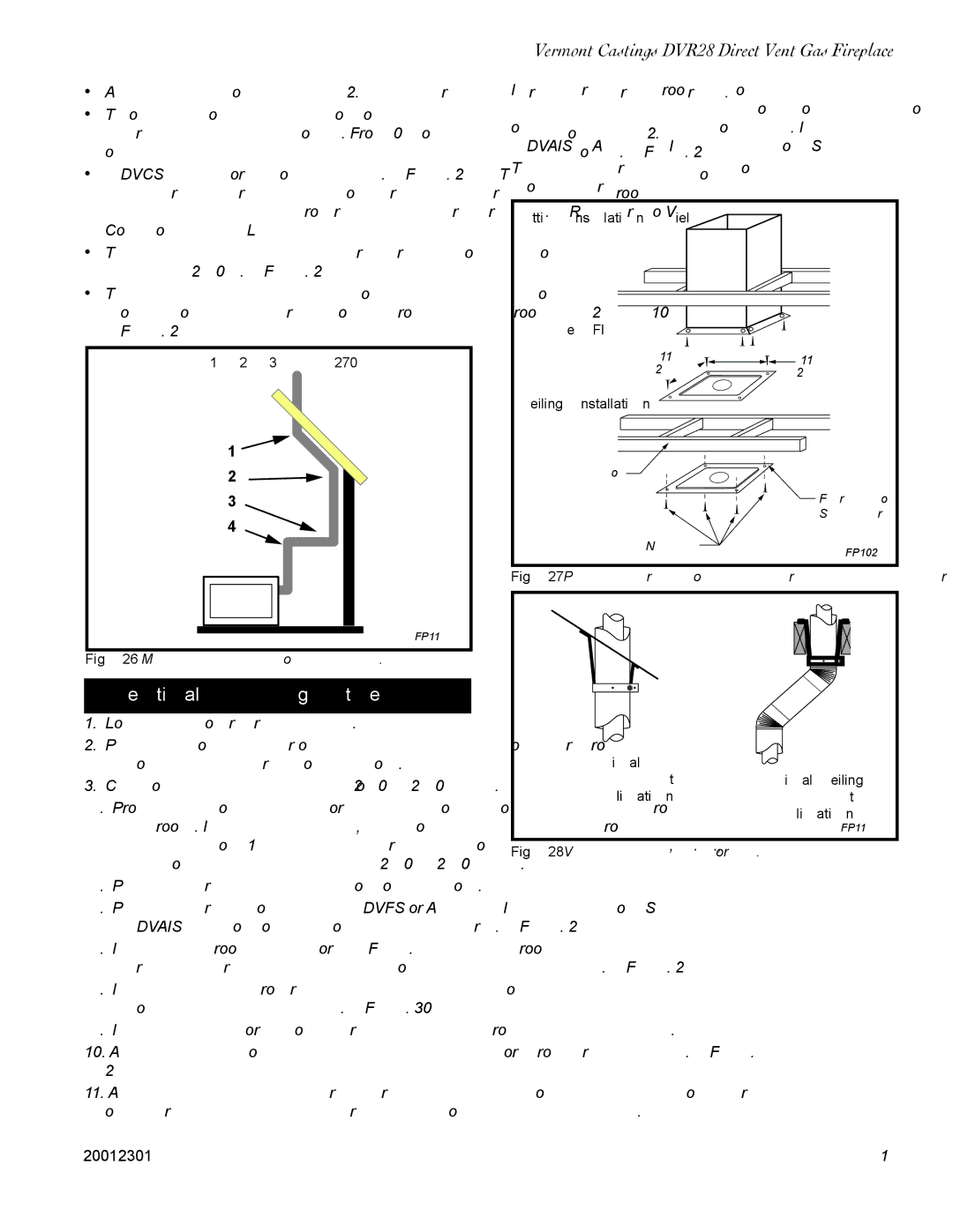
• Two sets of 45° elbow offsets may be used within the vertical sections. From 0 to a maximum of 8’ (2.5 m) of vent pipe can be used between elbows. (Fig. 26)
• 7DVCS supports offsets. (Fig. 28) This application will require that you first determine the roof pitch and use the appropriate starter kit. (Refer to Venting Components List)
• The maximum angular variation allowed in the sys- tem is 270°. (Fig. 26)
• The minimum height of the vent above the highest point of penetration through the roof is 2’ (610 mm). (Fig. 29)
1 + 2 + 3 + 4 = 270°
1 ![]()
2
3
4
FP1179
Fig. 26 Maximum elbow usage.
Vertical Through-the-Roof Installation
1.Locate your fireplace.
2.Plumb to center of the (4”) flue collar from ceiling above and mark position.
3.Cut opening equal to 9³⁄₈” x 9³⁄₈” (240 x 240 mm).
4.Proceed to plumb for additional openings through the roof. In all cases, the opening must provide a minimum of 1 inch clearance to the vent pipe, i.e., the hole must be at least 9³⁄₈” x 9³⁄₈” (240 x 240 mm).
5.Place fireplace into position.
6.Place firestop(s) #7DVFS or Attic Insulation Shield #7DVAIS into position and secure. (Fig. 27)
7.Install roof support (Fig. 44) and roof flashing making sure upper flange is below the shingles. (Fig. 28)
8.Install appropriate pipe sections until the venting is above the flashing. (Fig. 30)
9.Install storm collar and seal around the pipe.
10.Add additional vent lengths for proper height. (Fig. 29)
11.Apply high temperature sealant to 4” and 7” collars of vertical vent termination and install.
Vermont Castings DVR28 Direct Vent Gas Fireplace
If there is a room above ceiling level, fire stop spacer must be installed on both the bottom ad the top side of the ceiling joists. If an attic is above ceiling level a 7DVAIS (Attic Insulation Shield) must be installed.
The enlarged ends of the vent section always face downward.
Attic Insulation Shield
Upper Floor
11” | 11” | |
(279mm) | ||
(279mm) | ||
|
Ceiling Installation
Joist |
|
| Firestop |
| Spacer |
Nails (4) | FP1029 |
|
Fig. 27 Place firestop spacer(s) and secure.
|
|
|
|
|
|
|
|
|
|
|
|
|
|
|
|
|
|
|
|
|
|
|
|
|
|
|
|
|
|
|
|
|
|
|
|
|
|
|
|
|
|
|
|
|
|
|
|
|
|
|
|
|
|
|
|
|
|
|
|
|
|
|
|
Typical Roof |
|
|
|
|
| ||
|
|
|
|
| |||
Support | Typical Ceiling | ||||||
Application |
| Support | |||||
|
|
| Application | ||||
|
|
|
|
|
|
| FP1184 |
|
|
|
|
|
|
|
|
Fig. 28 Venting supports. |
|
|
|
|
| ||
20012301 | 15 |