Vermont Castings Radiance
Thermostat Connection (optional)
Use only a millivolt rated thermostat. Check the table below for the appropriate gauge thermostat wire to use for the length of lead required in your installation.
Thermostat |
|
Wire Gauge | / Maximum Run |
18 | 40 feet |
20 | 25 feet |
22 | 16 feet |
1.Install the wall thermostat in the desired location and run the wires to the stove location. Terminate these leads with 1/4" spade connectors.
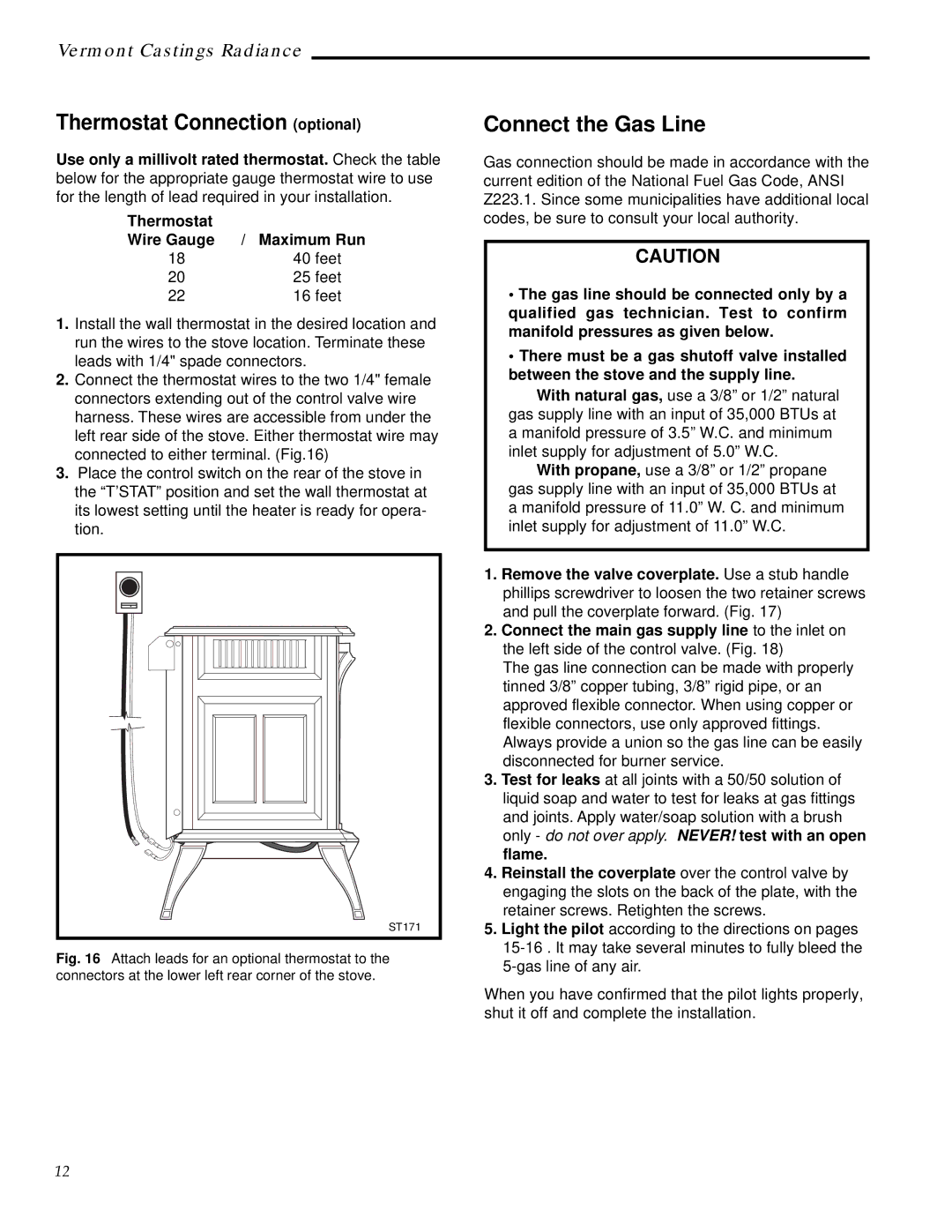
2.Connect the thermostat wires to the two 1/4" female connectors extending out of the control valve wire harness. These wires are accessible from under the left rear side of the stove. Either thermostat wire may connected to either terminal. (Fig.16)
3.Place the control switch on the rear of the stove in the “T’STAT” position and set the wall thermostat at its lowest setting until the heater is ready for opera- tion.
ST171
Fig. 16 Attach leads for an optional thermostat to the connectors at the lower left rear corner of the stove.
Connect the Gas Line
Gas connection should be made in accordance with the current edition of the National Fuel Gas Code, ANSI Z223.1. Since some municipalities have additional local codes, be sure to consult your local authority.
CAUTION
•The gas line should be connected only by a qualified gas technician. Test to confirm manifold pressures as given below.
•There must be a gas shutoff valve installed between the stove and the supply line.
With natural gas, use a 3/8” or 1/2” natural gas supply line with an input of 35,000 BTUs at a manifold pressure of 3.5” W.C. and minimum inlet supply for adjustment of 5.0” W.C.
With propane, use a 3/8” or 1/2” propane gas supply line with an input of 35,000 BTUs at a manifold pressure of 11.0” W. C. and minimum inlet supply for adjustment of 11.0” W.C.
1.Remove the valve coverplate. Use a stub handle phillips screwdriver to loosen the two retainer screws and pull the coverplate forward. (Fig. 17)
2.Connect the main gas supply line to the inlet on the left side of the control valve. (Fig. 18)
The gas line connection can be made with properly tinned 3/8” copper tubing, 3/8” rigid pipe, or an approved flexible connector. When using copper or flexible connectors, use only approved fittings. Always provide a union so the gas line can be easily disconnected for burner service.
3.Test for leaks at all joints with a 50/50 solution of liquid soap and water to test for leaks at gas fittings and joints. Apply water/soap solution with a brush only - do not over apply. NEVER! test with an open flame.
4.Reinstall the coverplate over the control valve by engaging the slots on the back of the plate, with the retainer screws. Retighten the screws.
5.Light the pilot according to the directions on pages
When you have confirmed that the pilot lights properly, shut it off and complete the installation.
12