VIVOTEK - A Leading Provider of Multimedia Communication Solutions
Network deployment
Setup the Network Camera over the Internet
This section explains how to configure the Network Camera to Internet connection.
1.If you have external devices such as sensors and alarms, make connection from general I/O terminal block.
2.Use the supplied RJ45 female/female coupler to connect the Network Camera to a switch. Use Catagory 5 Cross Cable when Network Camera is directly connected to PC.
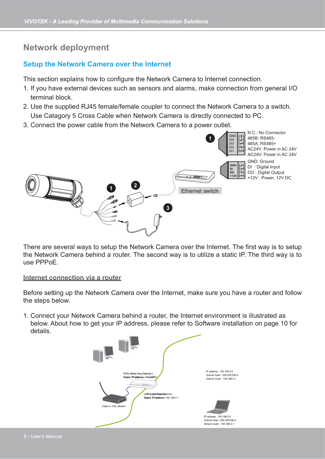
3. Connect the power cable from the Network Camera to a power outlet.
1
GND ![]()
![]() DI
DI ![]()
![]() DO
DO ![]()
![]() +12V
+12V ![]()
![]()
1 | 2 | |
Ethernet switch | ||
|
N.C.: No Connector
485B: RS485-
485A: RS485+
AC24V: Power in AC 24V
AC24V: Power in AC 24V
GND: Ground
DI : Digital Input
DO : Digital Output
+12V : Power, 12V DC
3
There are several ways to setup the Network Camera over the Internet. The first way is to setup the Network Camera behind a router. The second way is to utilize a static IP. The third way is to use PPPoE.
Internet connection via a router
Before setting up the Network Camera over the Internet, make sure you have a router and follow the steps below.
1.Connect your Network Camera behind a router, the Internet environment is illustrated as below. About how to get your IP address, please refer to Software installation on page 10 for details.
WAN (Wide Area Network )
IP address : 192.168.0.3
Subnet mask : 255.255.255.0
Internet
Router IP address : from ISP
Default router : 192.168.0.1
LAN (Local Area Network)
Router IP address : 192.168.0.1
Cable or DSL Modem
IP address : 192.168.0.2
Subnet mask : 255.255.255.0
Default router : 192.168.0.1
8 - User's Manual