Manuals
/
Vulcan-Hart
/
Kitchen Appliance
/
Oven
Vulcan-Hart
ML-044906, ML-044937 Pilot Adjustments, DIAGRAM #1 DIAGRAM #3, DIAGRAM #2, DIAGRAM #4
Models:
44963
ML-044905
ML-044908
ML-044907
ML-044906
ML-044909
ML-044964
ML-044938
ML-04494
ML-044939
ML-044961
ML-044969
ML-044962
ML-044936
ML-044937
1
10
52
52
Download
52 pages
17.34 Kb
7
8
9
10
11
12
13
14
Troubleshooting
Install
Parts list
DIAGRAM #1 DIAGRAM #3
Maintenance
Battery Installation
Gas Pressure Check Procedures
Burner Adjustments
Cleaning Procedures
Safety
Page 10
Image 10
Page 9
Page 11
Page 10
Image 10
Page 9
Page 11
Contents
SERVICE AND PARTS MANUAL
IMPORTANT FOR YOUR SAFETY
SIGNATURE SERIES
VULCAN-HART COMPANY
TABLE OF CONTENTS
Snorkel Oven and/or Electric Ignition Oven with KX Thermostat
Service Notes
INTRODUCTION
Product Features and Descriptions
Product Features and Descriptions Cont
UNCRATING/SETUP
INSTALLATION REQUIREMENTS
GAS PRESSURE REQUIREMENTS
GAS CONNECTIONS
Installation Requirements Cont
GAS PRESSURE CHECK PROCEDURES
Steps
VENTILATION REQUIREMENTS
DIAGRAM #2
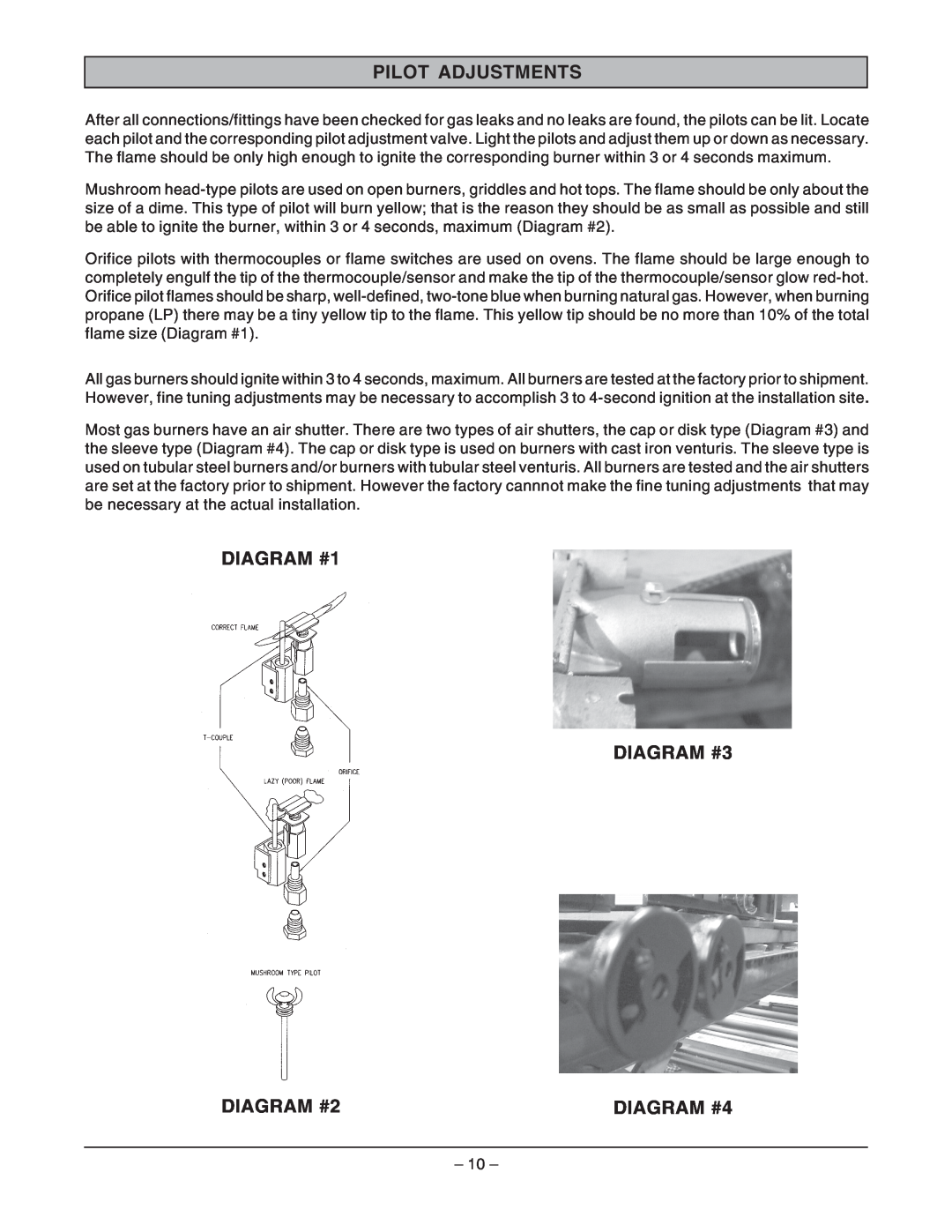
PILOT ADJUSTMENTS
DIAGRAM #1 DIAGRAM #3
DIAGRAM #4
BURNER ADJUSTMENTS
DIAGRAM #5
BATTERY INSTALLATION
DIAGRAM #6 DIAGRAM #7
DIAGRAM #8
THERMOSTATS
CALIBRATION OF THERMOSTATS
DIAGRAM #9
DIAGRAM #10
Standard Oven with FDTO Thermostat
Snorkel Oven and/or Electric Ignition Oven with KX Thermostat
Griddles with BJWA Thermostat
DIAGRAM #11 DIAGRAM #12
BYPASS SCREW CALIBRATION SCREW
OVEN ELECTRIC IGNITION SYSTEMS
Spark System
DIAGRAM #13
SIGNATURE OVEN W/SPARK PILOT
SIGNATURE CONVECTION OVEN
DIAGRAM #14
W/ELECTRIC IGNITION
DIAGRAM #15
SIGNATURE OVEN W/ELECTRIC IGNITION
BRASS VALVES
DIAGRAM #16
VALVE
DIAGRAM #18
DOORS, DOOR SEALS, HINGES AND COUNTERWEIGHTS
DIAGRAM #17
DIAGRAM #19
All sizes are rated for sea level
BURNER
ORIFICE, NAT
ORIFICE, LP
CLEANING PROCEDURES
Cleaning Tips
Recommended Service Frequency
SCHEDULED MAINTENANCE
Inspection Items
Problem
TROUBLESHOOTING
Probable Cause
Griddle will not heat evenly Product sticking to griddle
Problem
Gas odor
Charbroiler will not heat evenly Repeated component failure
Stainless steel turning blue Stainless steel turning brown
PARTS
Standard Burners
426745-1
Standard Burner Parts
KNOB CONTROL
Hot Tops/Fry Tops
426745-1
Hot Tops/Fry Tops Parts
KNOB CONTROL
French Top
426745-1
French Top Parts
KNOB CONTROL
Standard Oven
Convection Oven
Oven Parts
788278A 788276PANEL
Control System Convection Oven Control System Standard Oven
Control System Parts List
S TYPE
Body Parts/Shelves Risers
Body Parts/Shelves Risers Parts List 788382A1 788382A2 788382A3
788382A
Riser Kit Without Shelf P/N 788266A
Riser Kit With Single Shelf P/N 788365A
Double Deck Riser Kit Without Shelves P/N 788368A
Double Deck Riser Kit With Shelves P/N 788368A
FORM 31203 Rev. A March
Top
Page
Image
Contents