Vulcan-Hart ML-136590, VST4B operation manual Caster-Equippedbroilers, Burners & Ceramic Bricks

Models: VST4B ML-136590

1 24
Download 24 pages 61.9 Kb
Page 6
Image 6
CASTER-EQUIPPED BROILERS

2.Install two (2) hex head bolts per leg assembly to secure broiler body onto leg stand (Fig. 5). (Apply lock-tight to bolt threads.)

Hex-head

Bolts

Figure 5

CASTER-EQUIPPED BROILERS

Broilers mounted on stands with casters must use a flexible connector (not supplied) that complies with the Standard for Connectors for Movable Gas Appliances, ANSI Z21.69. CSA 6.16 and a quick-disconnect device that complies with the Standard for Quick- Disconnect Devices for use with Gas Fuel, ANSI-Z21-41.CSA 6.9. In addition, adequate means must be provided to limit movement of the broiler without depending on the connector and the quick-disconnect device or its associated piping to limit broiler movement. Attach the restraining device at the rear of the broiler. If disconnection of the restraint is necessary, turn off the gas supply before disconnection.

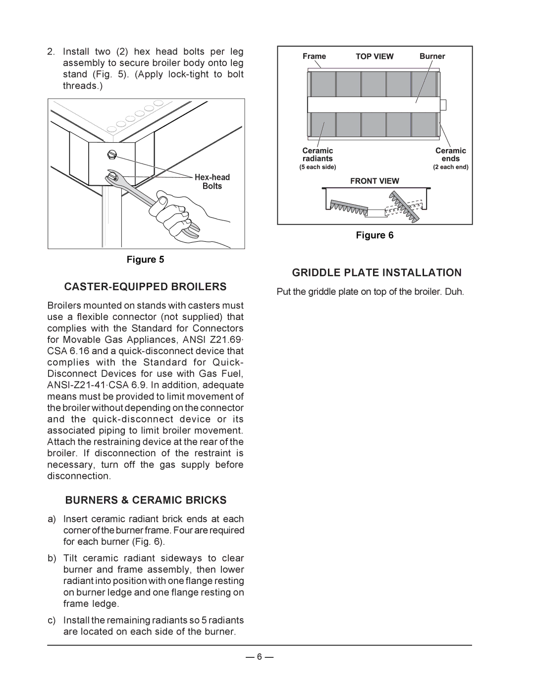
BURNERS & CERAMIC BRICKS

a)Insert ceramic radiant brick ends at each corner of the burner frame. Four are required for each burner (Fig. 6).

b)Tilt ceramic radiant sideways to clear burner and frame assembly, then lower radiant into position with one flange resting on burner ledge and one flange resting on frame ledge.

c)Install the remaining radiants so 5 radiants are located on each side of the burner.

Figure 6

GRIDDLE PLATE INSTALLATION

Put the griddle plate on top of the broiler. Duh.

— 6 —

Page 6
Image 6
Vulcan-Hart ML-136590, VST4B operation manual Caster-Equippedbroilers, Burners & Ceramic Bricks, Griddle Plate Installation