INSTALLATION
Top View
P
H1
A ![]()
N(See Below For Settings)
T ![]()
OM 0
STN ![]() RI/RO
RI/RO
S ![]() RI/RO
RI/RO
|
|
|
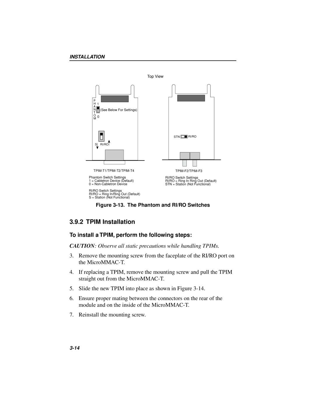
Phantom Switch Settings | RI/RO Switch Settings | |
1 | = Cabletron Device (Default) | RI/RO = Ring In Ring Out (Default) |
0 | = | STN = Station (Not Functional) |
RI/RO Switch Settings
RI/RO = Ring In/Ring Out (Default)
S = Station (Not Functional)
Figure 3-13. The Phantom and RI/RO Switches
3.9.2 TPIM Installation
To install a TPIM, perform the following steps:
CAUTION: Observe all static precautions while handling TPIMs.
3.Remove the mounting screw from the faceplate of the RI/RO port on the
4.If replacing a TPIM, remove the mounting screw and pull the TPIM straight out from the
5.Slide the new TPIM into place as shown in Figure
6.Ensure proper mating between the connectors on the rear of the module and on the inside of the
7.Reinstall the mounting screw.
