TROUBLESHOOTING
5.3 VIEWING POWER UP DIAGNOSTIC TESTS
The
NOTE: The LCD displays the following message whenever the POWER
UP DIAGNOSTIC test is running: “Cabletron Test in Progress.” See Section 5.2 for information about LCDs.
The testing process generates information and displays it on your terminal. The only time you can issue commands controlling the display of the information is when an error condition has been discovered.
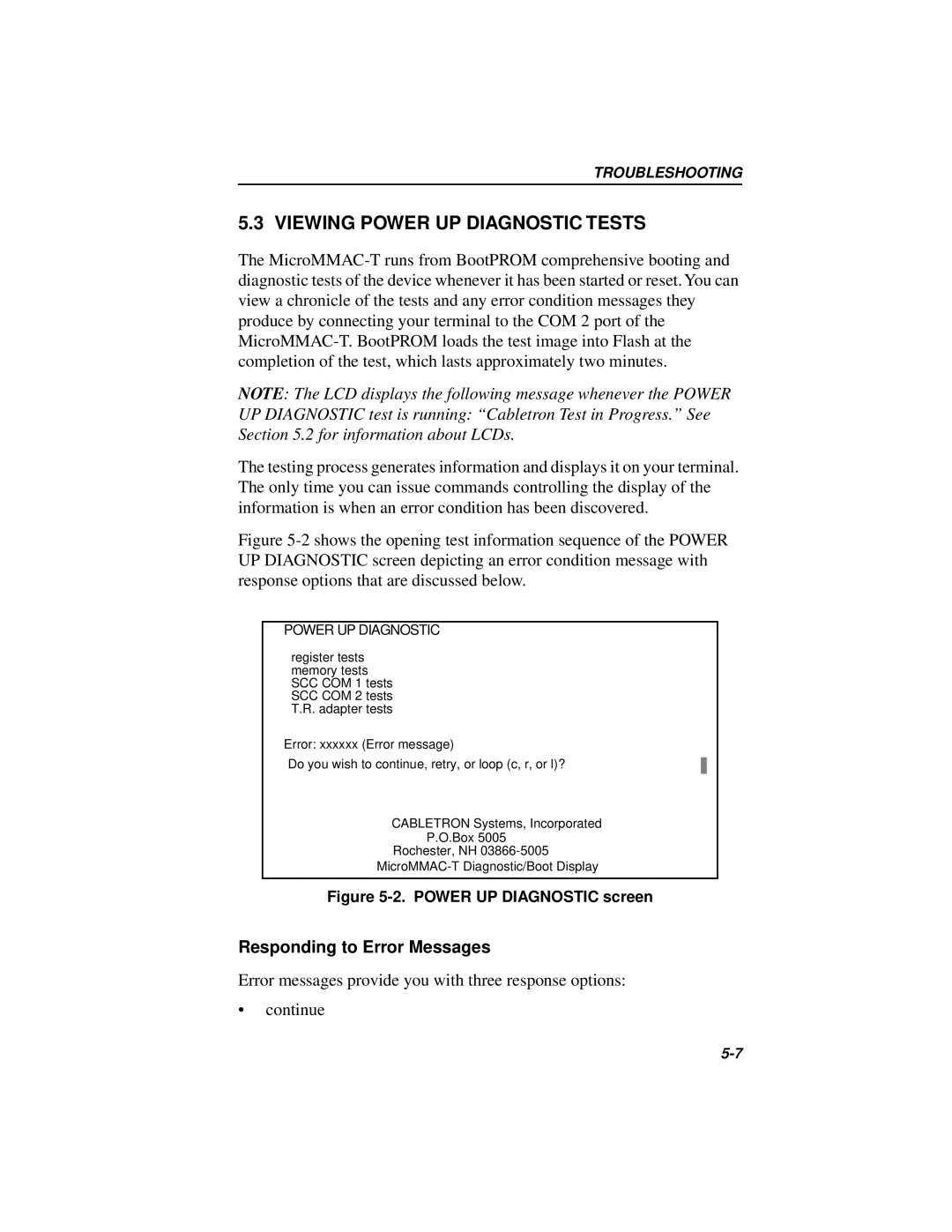
Figure 5-2 shows the opening test information sequence of the POWER UP DIAGNOSTIC screen depicting an error condition message with response options that are discussed below.
POWER UP DIAGNOSTIC
register tests memory tests SCC COM 1 tests SCC COM 2 tests T.R. adapter tests
Error: xxxxxx (Error message)
Do you wish to continue, retry, or loop (c, r, or l)? ![]()
![]()
CABLETRON Systems, Incorporated
P.O.Box 5005
Rochester, NH
Figure 5-2. POWER UP DIAGNOSTIC screen
Responding to Error Messages
Error messages provide you with three response options:
•continue