INSTALLATION
18
6
17
5
16
4
15
3
14
2
13
1
LNK
RI
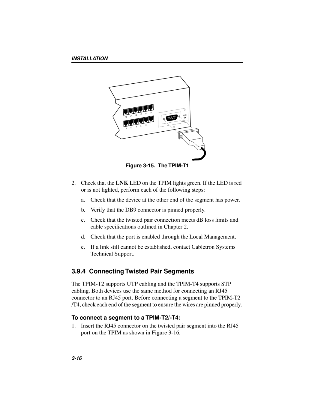
Figure 3-15. The TPIM-T1
2.Check that the LNK LED on the TPIM lights green. If the LED is red or is not lighted, perform each of the following steps:
a.Check that the device at the other end of the segment has power.
b.Verify that the DB9 connector is pinned properly.
c.Check that the twisted pair connection meets dB loss limits and cable specifications outlined in Chapter 2.
d.Check that the port is enabled through the Local Management.
e.If a link still cannot be established, contact Cabletron Systems Technical Support.
3.9.4 Connecting Twisted Pair Segments
The
To connect a segment to a TPIM-T2/-T4:
1.Insert the RJ45 connector on the twisted pair segment into the RJ45 port on the TPIM as shown in Figure