INSTALLATION
•The physical communication link consists of two strands of fiber optic cabling. The Transmit strand (TX) at one end connects to the Receive (RX) port at the other end and vice versa.
•Cabletron Systems labels its fiber optic cable to indicate which fiber is Receive and which is Transmit: one fiber is labeled 1, and the other fiber is labeled 2. If using a
CAUTION: Do not touch the ends of the fiber optic strands. Dust, dirt, and other contaminants on the ends of the strands create data transmissions problems. If the ends become dirty, clean them with alcohol using a soft, clean, lint free cloth.
To connect a fiber optic link segment to the TPIM-F2 /-F3:
1.Remove the protective plastic covers from the appropriate fiber optic ports on the module and from the ends of the connectors on each fiber strand.
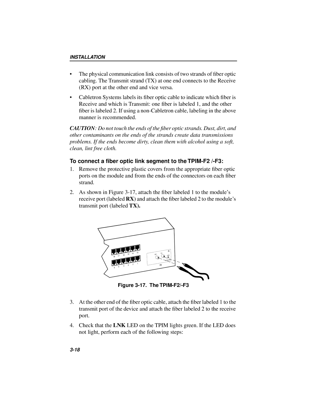
2.As shown in Figure
18
6
17
5
16
4
15
3
14
2
13
1
TX RX LNK
RI
Figure 3-17. The TPIM-F2/-F3
3.At the other end of the fiber optic cable, attach the fiber labeled 1 to the transmit port of the device and attach the fiber labeled 2 to the receive port.
4.Check that the LNK LED on the TPIM lights green. If the LED does not light, perform each of the following steps: