
6600 specifications
The Wayne-Dalton 6600 is a versatile and robust fiberglass garage door designed to meet the needs of residential homeowners who prioritize both aesthetics and durability. This innovative door stands out for its unique blend of features, technologies, and characteristics that cater to various styles and preferences.One of the standout features of the Wayne-Dalton 6600 is its superior insulation properties. The door is constructed with a high R-value, ensuring excellent thermal efficiency. This is particularly beneficial in regions with extreme temperatures, as it helps maintain a comfortable garage environment while potentially lowering energy costs for heating and cooling.
The Wayne-Dalton 6600 also boasts a lightweight design, making it easier to operate without compromising strength and durability. Unlike traditional steel doors, the fiberglass construction is resistant to rust and corrosion, ensuring longevity even in harsh weather conditions. Homeowners can enjoy peace of mind knowing that their investment is protected against the elements.
Aesthetically, the garage door is available in a variety of colors and finishes, allowing homeowners to customize their door to complement the overall design of their home. The realistic wood grain textures available add a touch of elegance and warmth, providing the classic look of wood without the maintenance associated with natural materials.
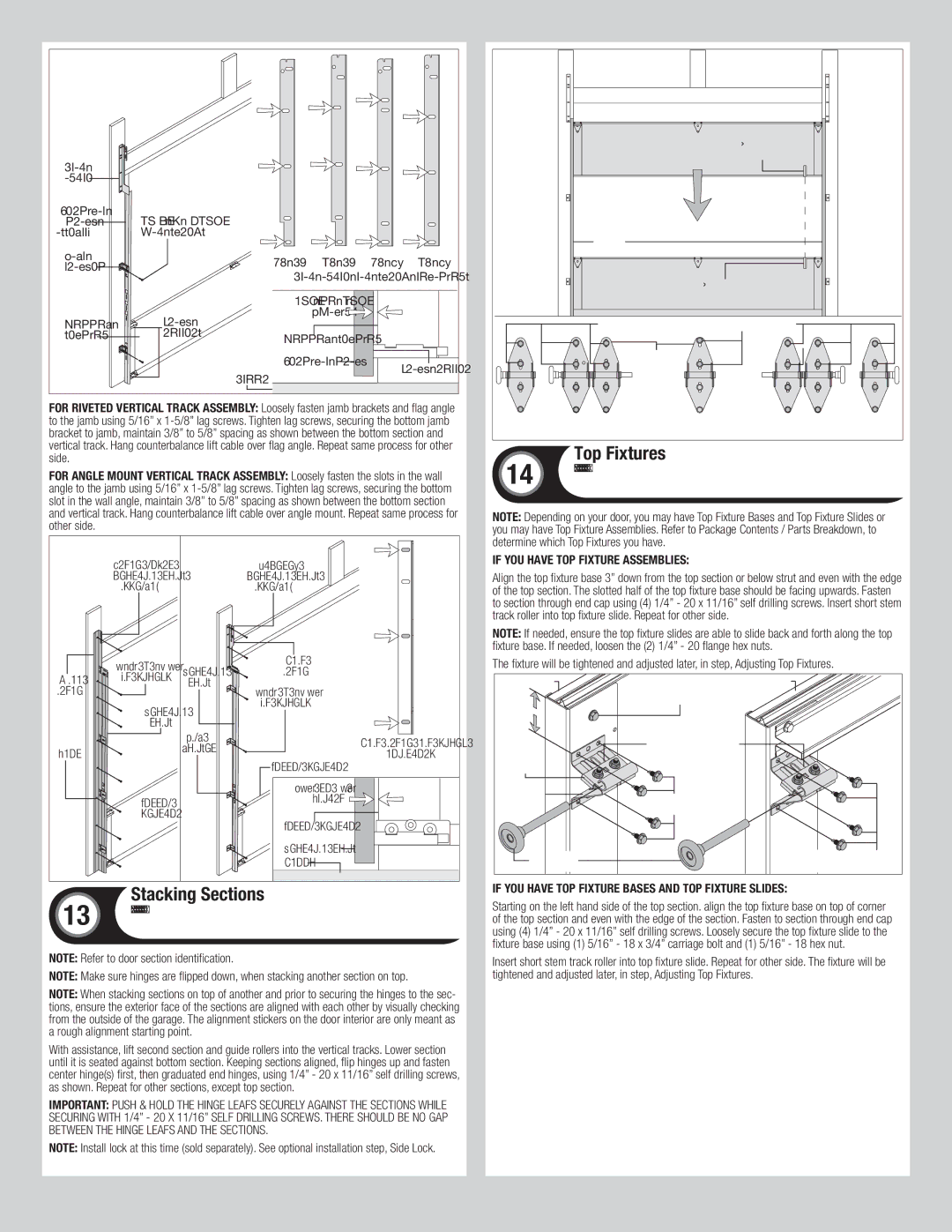
In terms of technology, the Wayne-Dalton 6600 incorporates a unique, high-quality pully and track system that ensures smooth operation. This system is designed to minimize wear and tear over time, enhancing the door's lifespan and performance. Additionally, the door is compatible with a range of smart home technologies, giving homeowners the convenience of remote access and control, enhancing security and ease of use.
Safety is a top priority for Wayne-Dalton, and the 6600 reflects this commitment with features such as pinch-resistant edges and an automatic reversal system that prevents accidents and injuries. The door is built to provide peace of mind for families, ensuring that the garage remains a safe space for both people and pets.
In conclusion, the Wayne-Dalton 6600 is an exemplary product for homeowners seeking a blend of functionality, style, and safety. With its innovative materials, customizability, and advanced technology, it offers a reliable and attractive solution for any home’s garage door needs. Homeowners who invest in the Wayne-Dalton 6600 can expect unmatched performance and enduring beauty for years to come.