Operating Instructions & Parts Manual | JSU50 |
Installation (Continued)
Pressure | Prime Plug |
Switch |
|
| Inlet |
| Drain |
Air Valve | Fitting |
| |
| |
1/2 HP, 3/4 HP, & 1 HP |
|
Figure 5 - Shallow Well Pump
Precharged Tank
3.Insure tank is secured to the floor or base.
4.Bolt pump to the floor or the mounting bracket on tank.
5.Set air pressure in tank to desired level. An air valve is located on the side and will accept a standard fitting from a bicycle pump or air line.
6.Install a valve and an isolator hose between the tank and the house plumbing. This will reduce the noise level of the pump system and aid in servicing.
7.Provide a hose bib (faucet) at the lowest point in the system to drain the system for service or storage.
8.Slope horizontal lines up toward pump a minimum of 1/4" per foot. This will prevent trapping air in the lines.
electrical connections
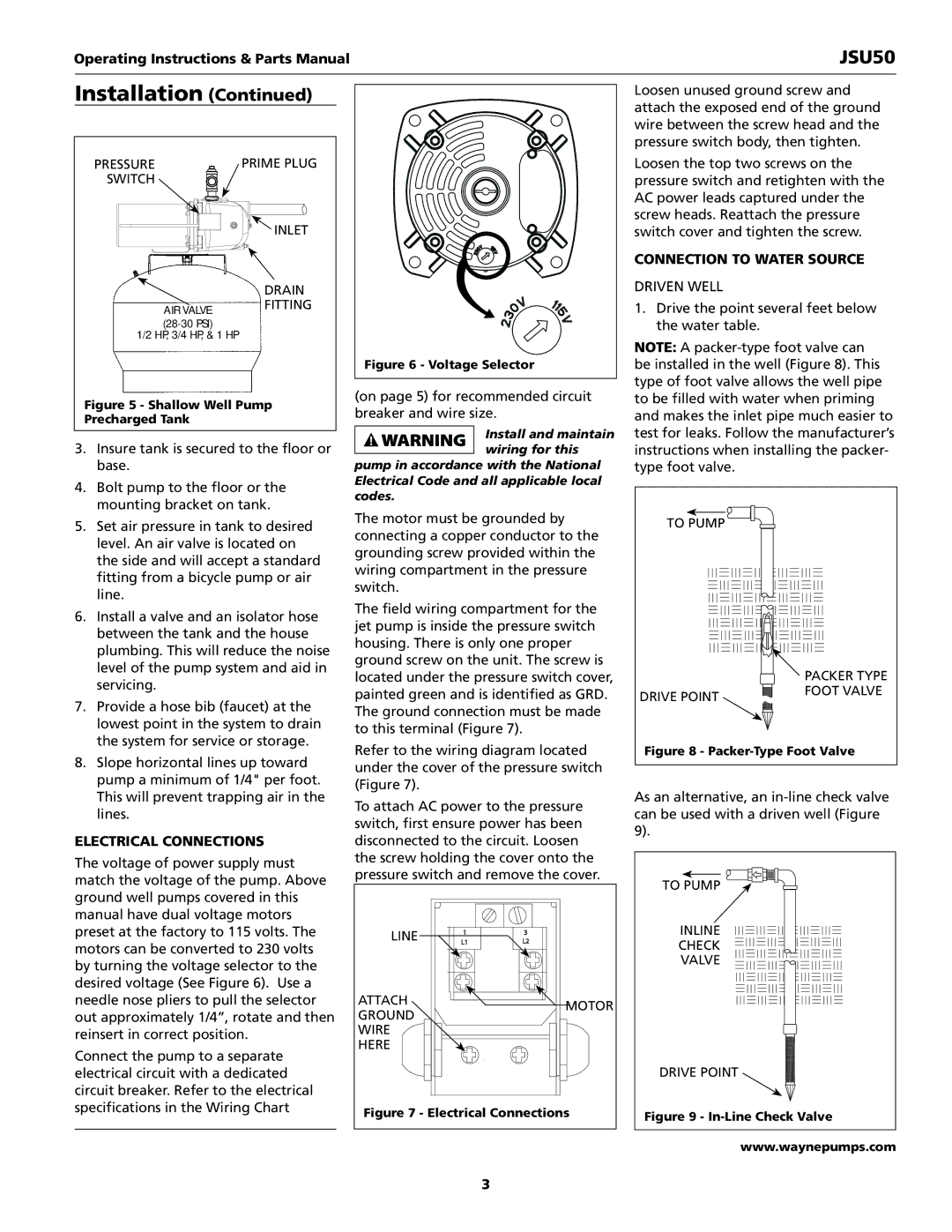
The voltage of power supply must match the voltage of the pump. Above ground well pumps covered in this manual have dual voltage motors preset at the factory to 115 volts. The motors can be converted to 230 volts by turning the voltage selector to the desired voltage (See Figure 6). Use a needle nose pliers to pull the selector out approximately 1/4”, rotate and then reinsert in correct position.
Connect the pump to a separate electrical circuit with a dedicated circuit breaker. Refer to the electrical specifications in the Wiring Chart
Figure 6 - Voltage Selector
(on page 5) for recommended circuit breaker and wire size.
Install and maintain wiring for this
pump in accordance with the National Electrical Code and all applicable local codes.
The motor must be grounded by connecting a copper conductor to the grounding screw provided within the wiring compartment in the pressure switch.
The field wiring compartment for the jet pump is inside the pressure switch housing. There is only one proper ground screw on the unit. The screw is located under the pressure switch cover, painted green and is identified as GRD. The ground connection must be made to this terminal (Figure 7).
Refer to the wiring diagram located under the cover of the pressure switch (Figure 7).
To attach AC power to the pressure switch, first ensure power has been disconnected to the circuit. Loosen the screw holding the cover onto the pressure switch and remove the cover.
Line | 1 | 3 |
| ||
| L1 | L2 |
Attach |
| Motor |
Ground |
| |
|
| |
Wire |
|
|
Here |
|
|
Figure 7 - Electrical Connections
Loosen unused ground screw and attach the exposed end of the ground wire between the screw head and the pressure switch body, then tighten.
Loosen the top two screws on the pressure switch and retighten with the AC power leads captured under the screw heads. Reattach the pressure switch cover and tighten the screw.
connection to water source
Driven Well
1.Drive the point several feet below the water table.
Note: A
To pump
| Packer Type |
Drive Point | Foot Valve |
|
Figure 8 - Packer-Type Foot Valve
As an alternative, an
To pump
Inline
Check
Valve
Drive Point
Figure 9 - In-Line Check Valve
www.waynepumps.com
3