Step 16
Add fuel scale
You will need: fuel scale assembly, two
Insert indicator rod of fuel scale through the elongated hole in the right end panel. Figure 18 (a).
Slip the bolts on the back of the fuel scale assembly through the two small holes in the right end panel and tank panel. Add washers, then wing nuts and tighten. Figure 18 (b).
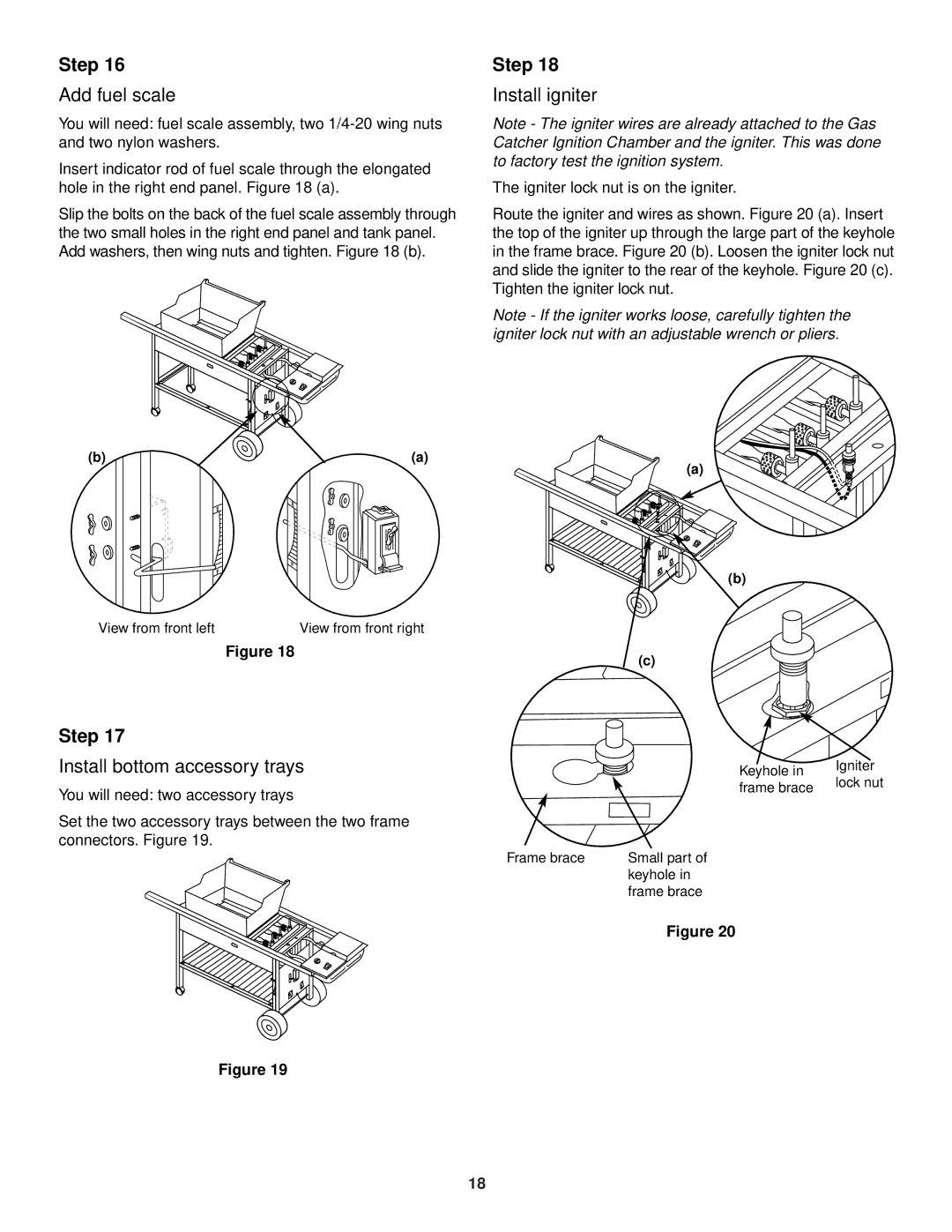
Step 18
Install igniter
Note - The igniter wires are already attached to the Gas Catcher Ignition Chamber and the igniter. This was done to factory test the ignition system.
The igniter lock nut is on the igniter.
Route the igniter and wires as shown. Figure 20 (a). Insert the top of the igniter up through the large part of the keyhole in the frame brace. Figure 20 (b). Loosen the igniter lock nut and slide the igniter to the rear of the keyhole. Figure 20 (c). Tighten the igniter lock nut.
Note - If the igniter works loose, carefully tighten the igniter lock nut with an adjustable wrench or pliers.
(b) | (a) |
| E |
| E |
| F |
| F |
View from front left | View from front right |
Figure 18
Step 17
Install bottom accessory trays
You will need: two accessory trays
Set the two accessory trays between the two frame connectors. Figure 19.
(a)
(b)
(c)
Keyhole in | Igniter | |
lock nut | ||
frame brace | ||
|
Frame brace | Small part of |
| keyhole in |
| frame brace |
| Figure 20 |
Figure 19
18