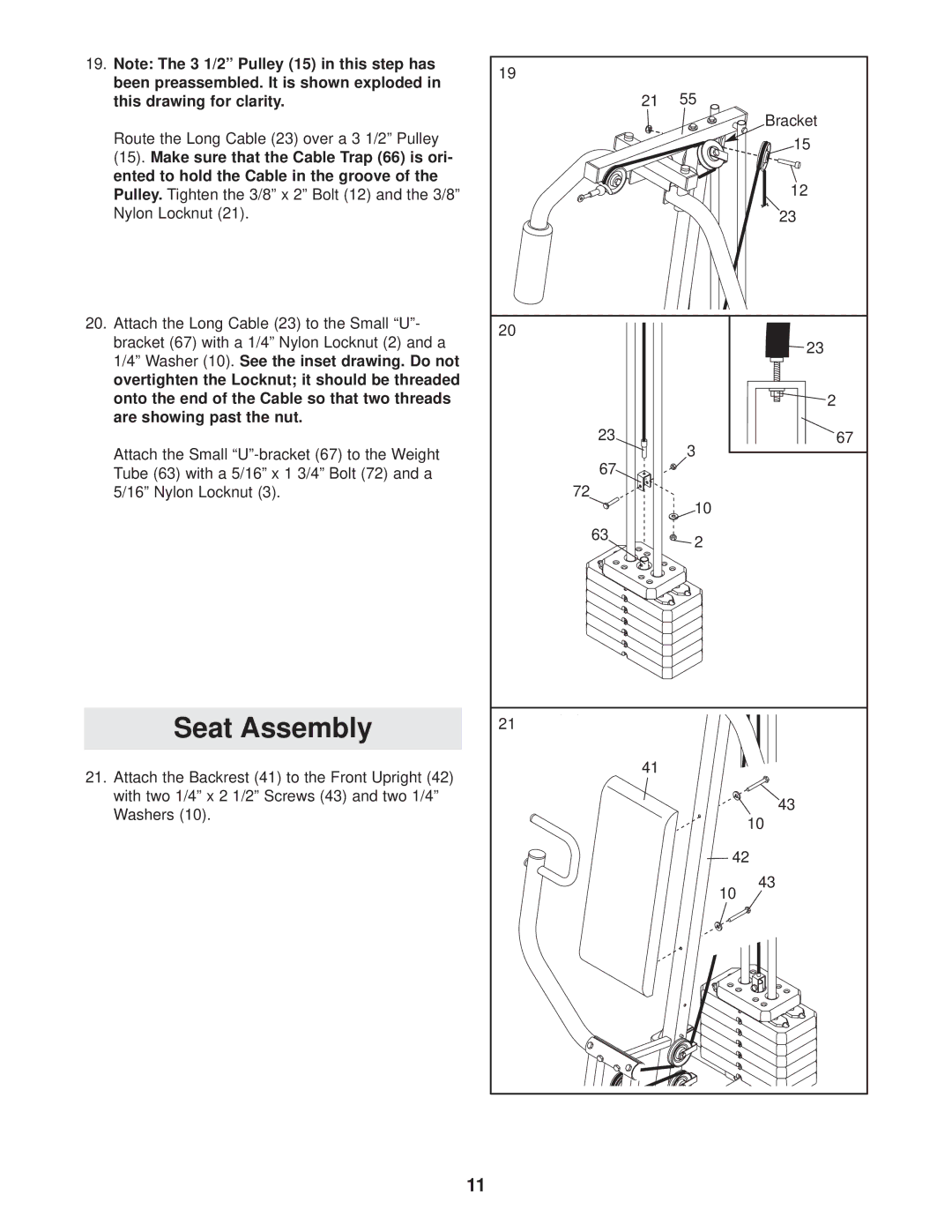
19.Note: The 3 1/2” Pulley (15) in this step has been preassembled. It is shown exploded in this drawing for clarity.
Route the Long Cable (23) over a 3 1/2” Pulley
(15). Make sure that the Cable Trap (66) is ori- ented to hold the Cable in the groove of the Pulley. Tighten the 3/8” x 2” Bolt (12) and the 3/8” Nylon Locknut (21).
20.Attach the Long Cable (23) to the Small “U”- bracket (67) with a 1/4” Nylon Locknut (2) and a 1/4” Washer (10).See the inset drawing. Do not overtighten the Locknut; it should be threaded onto the end of the Cable so that two threads are showing past the nut.
Attach the Small
Seat Assembly
21.Attach the Backrest (41) to the Front Upright (42) with two 1/4” x 2 1/2” Screws (43) and two 1/4” Washers (10).
19 |
|
21 | 55 |
| Bracket |
| 15 |
| 12 |
| 23 |
20 | 23 |
| |
| 2 |
23 | 67 |
| 3 |
67 |
|
72 | 10 |
| |
63 | 2 |
| |
21 |
|
41 |
|
| 43 |
| 10 |
| 42 |
| 43 |
| 10 |
11