ASSEMBLY
Make Things Easier for Yourself
Everything in this manual is designed to ensure that the weight system can be assembled suc- cessfully by anyone. However, it is important to realize that the weight system has many parts and that the assembly process will take time. Most people find that by setting aside plenty of time, assembly will go smoothly.
•Assembly requires two people.
•Place all parts in a cleared area and remove the packing materials. Do not dispose of the packing materials until assembly is completed.
•Tighten all parts as you assemble them, unless instructed to do otherwise.
•As you assemble the weight system, make sure all parts are oriented as shown in the drawings.
•For help identifying small parts, use the PART IDENTIFICATION CHART at the center of this manual.
The following tools (not included) are required for assembly:
• Two adjustable wrenches
• One rubber mallet
• One standard screwdriver
• One Phillips screwdriver
•Lubricant, such as grease or petroleum jelly, and soapy water.
Assembly will be more convenient if you have a socket set, a set of
1.
Frame Assembly
Before beginning assembly, make sure that you have read and understand the informa- tion in the box above.
For help identifying small parts, use the PART IDENTIFICATION CHART in the cen- ter of this manual.
1 |
3 |
4 |
79 |
79 |
1 |
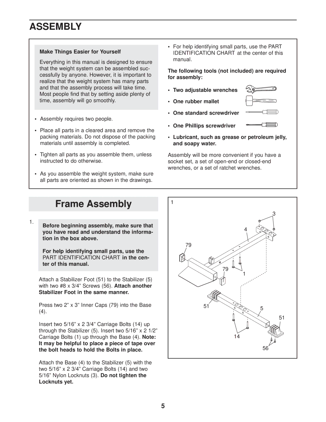
Attach a Stabilizer Foot (51) to the Stabilizer (5) with two #8 x 3/4” Screws (56).Attach another
Stabilizer Foot in the same manner.
Press two 2” x 3” Inner Caps (79) into the Base
(4).
Insert two 5/16” x 2 3/4” Carriage Bolts (14) up through the Stabilizer (5). Insert two 5/16” x 2 1/2” Carriage Bolts (1) up through the Base (4). Note:
It may be helpful to place a piece of tape over the bolt heads to hold the Bolts in place.
Attach the Base (4) to the Stabilizer (5) with the two 5/16” x 2 3/4” Carriage Bolts (14) and two 5/16” Nylon Locknuts (3).Do not tighten the
Locknuts yet.
51 | 5 |
| |
| 51 |
| 14 |
| 56 |
5