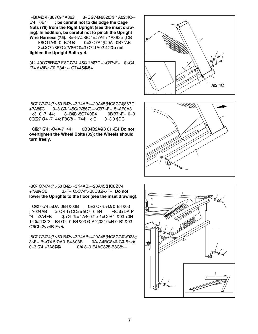
2. Insert the Right Upright (74) into the indicated bracket on | 2 |
|
|
|
|
|
|
|
|
the Base (83); be careful not to dislodge the Cage |
| 75 |
|
|
|
|
| ||
Nuts (76) from the Right Upright (see the inset draw- |
|
|
|
|
|
|
| ||
ing). In addition, be careful not to pinch the Upright |
|
|
|
|
|
| 74 |
|
|
Wire Harness (75). Finger tighten three Upright Bolts |
|
|
|
|
|
|
|
| |
(72) with three Washers (78) and three Star Washers |
|
|
|
|
|
|
|
|
|
(71) into the Right Upright and the bracket. Do not |
|
|
|
|
|
|
| 71 78 72 | |
tighten the Upright Bolts yet. |
|
|
|
|
|
| 78 | ||
Repeat this step with the Left Upright (not shown). Note: |
| 76 |
|
|
| 72 |
|
| |
There is not a wire on the left side. |
|
|
|
|
| 83 |
| ||
|
|
|
|
|
|
| 71 |
| |
|
|
|
|
|
|
| Bracket |
| |
3. With the help of a second person, carefully tip the Right | 3 |
|
|
|
|
|
|
|
|
Upright (74) and the Left Upright (not shown) forward. |
|
|
|
|
|
|
|
| |
Hold a Wheel (86) inside of the Base (83) as shown, and |
|
|
|
|
|
|
|
| 74 |
attach the Wheel with a Wheel Bolt (85) and a Nut (38). |
|
|
|
|
|
|
|
| |
Attach the other Wheel (86) as described above. Do not |
|
|
|
|
|
|
|
|
|
overtighten the Wheel Bolts (85); the Wheels should |
|
|
|
|
|
|
|
|
|
turn freely. |
|
|
|
|
|
|
|
|
|
|
| 38 |
|
|
|
| 83 |
|
|
|
|
| 86 |
|
| 85 |
|
| |
|
|
|
|
|
|
|
| ||
4. With the help of a second person, carefully tip the | 4 |
|
|
|
| 73 | 77 |
| |
Uprights (73, 74) down to the position shown. Do not |
|
|
|
| 81 | ||||
lower the Uprights to the floor (see the inset drawing). |
|
|
|
|
|
|
|
| |
Attach the four Base Pads (81) and the four Base Pad |
|
|
|
|
|
|
|
| 82 |
Spacers (77) to the bottom of the Base (83) with four 1” |
|
|
|
|
|
|
|
| |
Tek Screws (82). Note: One replacement Base Pad may |
| 77 |
|
|
|
|
|
|
|
be included. Use the Base Pad to replace any Base Pad |
| 81 82 |
|
| 83 | ||||
that becomes worn. |
|
|
|
| |||||
With the help of a second person, carefully tip the treadill |
|
|
|
|
|
|
| 77 |
|
down so the four Base Pads (81) are resting on the floor | 74 |
|
|
|
|
|
|
| |
and the Uprights (73, 74) are in a vertical position. |
|
|
|
|
|
| 81 82 | ||
|
|
| 77 | 81 |
|
|
| 73, 74 |
|
|
|
| 82 |
|
|
| |||
|
|
|
|
|
|
|
| ||
7