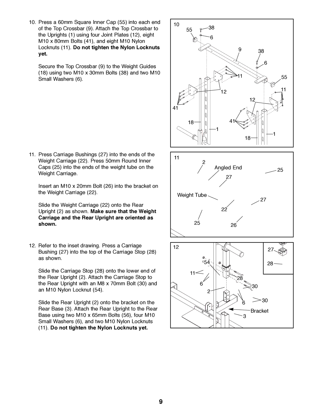
10. Press a 60mm Square Inner Cap (55) into each end | 10 | 38 |
|
of the Top Crossbar (9). Attach the Top Crossbar to |
| ||
55 |
| ||
the Uprights (1) using four Joint Plates (12), eight |
| 6 |
|
M10 x 80mm Bolts (41), and eight M10 Nylon |
|
| |
|
|
| |
Locknuts (11). Do not tighten the Nylon Locknuts |
| 9 | 38 |
yet. |
| ||
|
| ||
|
|
| |
Secure the Top Crossbar (9) to the Weight Guides |
|
| 6 |
|
|
| |
(18) using two M10 x 30mm Bolts (38) and two M10 |
| 11 | 55 |
Small Washers (6). |
| ||
|
|
| |
|
| 12 | 11 |
|
|
| |
|
|
| 12 |
| 41 |
|
|
| 18 | 41 |
|
|
| 1 | 1 |
|
|
| |
|
|
| 18 |
11. Press Carriage Bushings (27) into the ends of the | 11 |
|
|
Weight Carriage (22). Press 50mm Round Inner | 2 |
| |
|
| ||
Caps (25) into the ends of the weight tube on the |
| Angled End | 25 |
Weight Carriage. |
|
| |
| 27 |
| |
|
|
|
Insert an M10 x 20mm Bolt (26) into the bracket on |
|
the Weight Carriage (22). | Weight Tube |
|
Slide the Weight Carriage (22) onto the Rear |
|
| 27 |
| 22 |
| |
Upright (2) as shown. Make sure that the Weight |
|
| |
|
|
| |
Carriage and the Rear Upright are oriented as | 25 |
|
|
shown. | 26 |
| |
12. Refer to the inset drawing. Press a Carriage | 12 |
| 27 |
Bushing (27) into the top of the Carriage Stop (28) |
|
| |
|
|
| |
as shown. | 54 |
| 28 |
|
| ||
Slide the Carriage Stop (28) onto the lower end of | 11 |
|
|
the Rear Upright (2). Attach the Carriage Stop to | 28 |
| |
|
| ||
the Rear Upright with an M8 x 70mm Bolt (30) and | 6 |
| 30 |
an M10 Nylon Locknut (54). | 2 |
| |
|
| ||
|
|
| |
Slide the Rear Upright (2) onto the bracket on the |
| 6 | 30 |
|
| ||
Rear Base (3). Attach the Rear Upright to the Rear |
|
| Bracket |
Base using two M10 x 65mm Bolts (56), four M10 |
| 3 | |
|
| ||
Small Washers (6), and two M10 Nylon Locknuts |
|
|
|
(11). Do not tighten the Nylon Locknuts yet. |
|
|
|
9
