ARM ASSEMBLY
CABLE ASSEMBLY
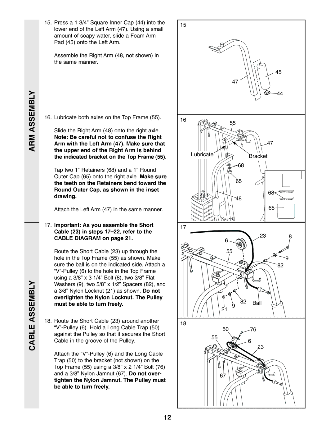
15. Press a 1 3/4” Square Inner Cap (44) into the | 15 |
|
|
|
lower end of the Left Arm (47). Using a small |
|
|
| |
|
|
|
| |
amount of soapy water, slide a Foam Arm |
|
|
|
|
Pad (45) onto the Left Arm. |
|
|
|
|
Assemble the Right Arm (48, not shown) in |
|
|
|
|
the same manner. |
|
|
|
|
|
|
|
| 45 |
|
| 47 |
|
|
|
|
|
| 44 |
16. Lubricate both axles on the Top Frame (55). | 16 | 55 |
|
|
|
|
| ||
|
|
|
| |
Slide the Right Arm (48) onto the right axle. |
|
|
|
|
Note: Be careful not to confuse the Right |
|
| 47 |
|
Arm with the Left Arm (47). Make sure that |
|
|
| |
the upper end of the Right Arm is behind | Lubricate |
| Bracket |
|
the indicated bracket on the Top Frame (55). |
|
| ||
|
|
| ||
Tap two 1” Retainers (68) and a 1” Round |
| 68 |
|
|
|
|
|
| |
Outer Cap (65) onto the right axle. Make sure |
| 65 |
|
|
the teeth on the Retainers bend toward the |
|
|
| |
|
|
|
| |
Round Outer Cap, as shown in the inset |
|
| 68 |
|
drawing. |
| 48 |
| |
|
|
| ||
|
|
|
| |
Attach the Left Arm (47) in the same manner. |
|
| 65 |
|
17. Important: As you assemble the Short | 17 |
|
|
|
Cable (23) in steps |
|
|
| |
|
| 23 | 8 | |
CABLE DIAGRAM on page 21. | 6 |
| ||
|
|
|
| |
Route the Short Cable (23) up through the | 55 |
|
| |
hole in the Top Frame (55) as shown. Make |
|
|
| 9 |
sure the ball is on the indicated side. Attach a |
|
|
| 82 |
|
|
|
| |
using a 3/8” x 3 1/4” Bolt (8), two 3/8” Flat |
|
|
|
|
Washers (9), two 5/8” x 1/2” Spacers (82), and |
|
|
|
|
a 3/8” Nylon Locknut (21) as shown. Do not |
|
|
|
|
overtighten the Nylon Locknut. The Pulley |
| 82 | Ball |
|
must be able to turn freely. |
|
| ||
| 21 | 9 |
|
|
18. Route the Short Cable (23) around another | 18 |
|
|
|
|
|
| ||
50 |
| 76 |
| |
against the Pulley so that it secures the Short |
|
| ||
55 |
|
|
| |
Cable in the groove of the Pulley. |
| 6 |
| |
|
|
| ||
|
|
| 23 |
|
Attach the |
|
|
|
|
Trap (50) to the bracket (not shown) on the |
|
|
|
|
Top Frame (55) using a 3/8” x 2 1/4” Bolt (76) |
|
|
|
|
and a 3/8” Nylon Jamnut (67). Do not over- | 67 |
|
|
|
tighten the Nylon Jamnut. The Pulley must |
|
|
| |
|
|
|
| |
be able to turn freely. |
|
|
|
|
12