ATTACHING THE ACCESSORIES
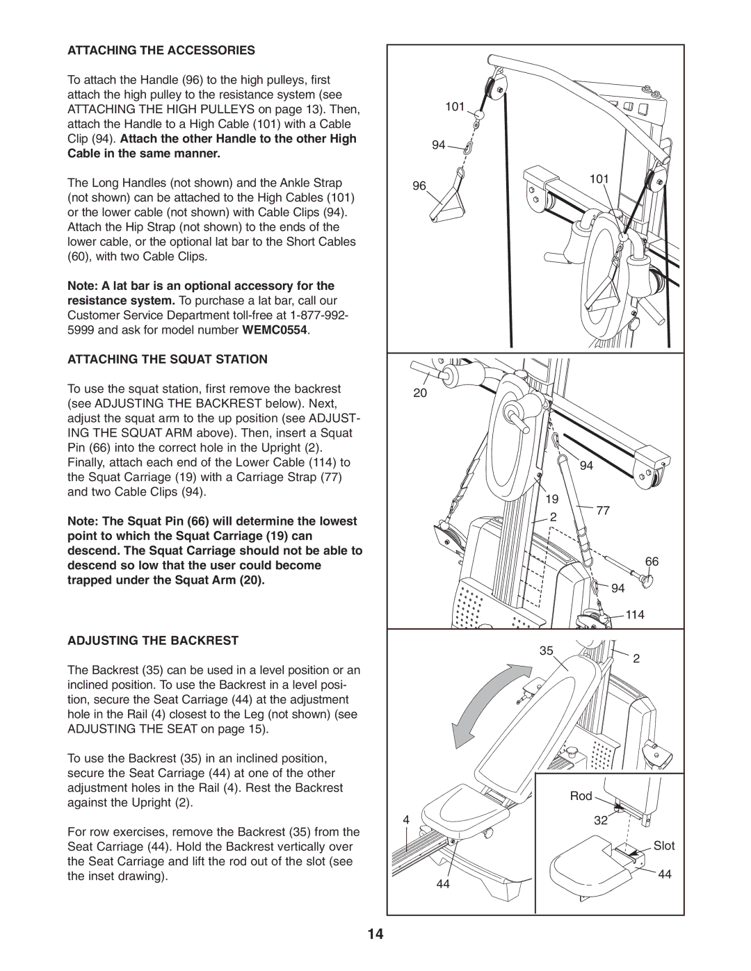
To attach the Handle (96) to the high pulleys, first attach the high pulley to the resistance system (see ATTACHING THE HIGH PULLEYS on page 13). Then, attach the Handle to a High Cable (101) with a Cable Clip (94). Attach the other Handle to the other High
Cable in the same manner.
The Long Handles (not shown) and the Ankle Strap (not shown) can be attached to the High Cables (101) or the lower cable (not shown) with Cable Clips (94). Attach the Hip Strap (not shown) to the ends of the lower cable, or the optional lat bar to the Short Cables (60), with two Cable Clips.
Note: A lat bar is an optional accessory for the resistance system. To purchase a lat bar, call our Customer Service Department
ATTACHING THE SQUAT STATION
To use the squat station, first remove the backrest (see ADJUSTING THE BACKREST below). Next, adjust the squat arm to the up position (see ADJUST- ING THE SQUAT ARM above). Then, insert a Squat Pin (66) into the correct hole in the Upright (2). Finally, attach each end of the Lower Cable (114) to the Squat Carriage (19) with a Carriage Strap (77) and two Cable Clips (94).
Note: The Squat Pin (66) will determine the lowest point to which the Squat Carriage (19) can descend. The Squat Carriage should not be able to descend so low that the user could become trapped under the Squat Arm (20).
ADJUSTING THE BACKREST
The Backrest (35) can be used in a level position or an inclined position. To use the Backrest in a level posi- tion, secure the Seat Carriage (44) at the adjustment hole in the Rail (4) closest to the Leg (not shown) (see ADJUSTING THE SEAT on page 15).
To use the Backrest (35) in an inclined position, secure the Seat Carriage (44) at one of the other adjustment holes in the Rail (4). Rest the Backrest against the Upright (2).
For row exercises, remove the Backrest (35) from the Seat Carriage (44). Hold the Backrest vertically over the Seat Carriage and lift the rod out of the slot (see the inset drawing).
|
| 101 |
|
|
| 94 |
|
| 96 |
| 101 |
|
|
| |
| 20 |
|
|
|
|
| 94 |
|
| 19 | 77 |
|
| 2 | |
|
|
| |
|
|
| 66 |
|
|
| 94 |
|
|
| 114 |
|
| 35 | 2 |
|
|
| |
|
|
| Rod |
4 |
|
| 32 |
|
|
| Slot |
|
| 44 | 44 |
|
|
|
14
