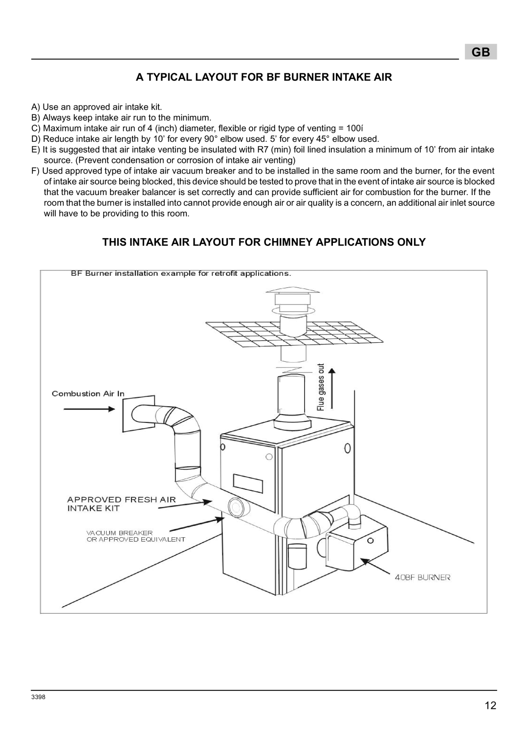
800061000-Brn-PO Rie BF5, 800060000-Brn-PO Rie BF5, 800062000-Brn-PO Rie BF5 specifications
The Weil-McLain 800060000-Brn-PO Rie BF5, 800062000-Brn-PO Rie BF5, and 800061000-Brn-PO Rie BF5 are part of the manufacturer’s premier line of residential and commercial heating solutions. Renowned for their durability, efficiency, and advanced engineering, these models are designed to meet the diverse heating demands of modern buildings.One of the standout features of the Weil-McLain Rie BF5 series is their robust construction. These boilers are typically built with high-grade cast iron, which not only enhances their longevity but also ensures superior heat retention. This design allows the boilers to operate efficiently over extended periods, minimizing the need for repairs and replacements.
Efficiency is a critical factor in today’s heating systems, and the Weil-McLain BF5 series excels in this category. With energy-efficient ratings, they are designed to reduce energy consumption while maintaining optimal performance. This leads to lower utility bills for homeowners and businesses alike, contributing to overall cost savings.
The technology integrated into the Rie BF5 series also plays a pivotal role in their operation. Advanced combustion technology ensures clean, efficient burning of fuel. This results in lower emissions, making these units a more environmentally friendly choice. Additionally, the incorporation of modulating gas valves allows for precise control of the heating output, enhancing comfort levels while reducing energy wastage.
Another notable characteristic is the versatility of the BF5 series. They come in various output capacities, making them suitable for a wide range of heating applications, from small residential spaces to larger commercial environments. The compact design also facilitates easier installation, making it simpler for contractors to integrate them into existing systems.
Moreover, the Weil-McLain Rie BF5 series is equipped with user-friendly controls that provide homeowners and facility managers with the ability to monitor and adjust settings as needed. This feature not only enhances user convenience but also contributes to overall performance optimization.
In conclusion, the Weil-McLain 800060000-Brn-PO Rie BF5, 800062000-Brn-PO Rie BF5, and 800061000-Brn-PO Rie BF5 embody advanced heating technology, exceptional efficiency, and durable construction. These characteristics make them an excellent choice for those seeking reliable heating solutions that stand the test of time while being environmentally conscious. Whether for residential or commercial use, these boilers deliver consistent performance and comfort, making them a trusted option in the industry.

