BMC and
WIRING TO MODULATING MOTORS
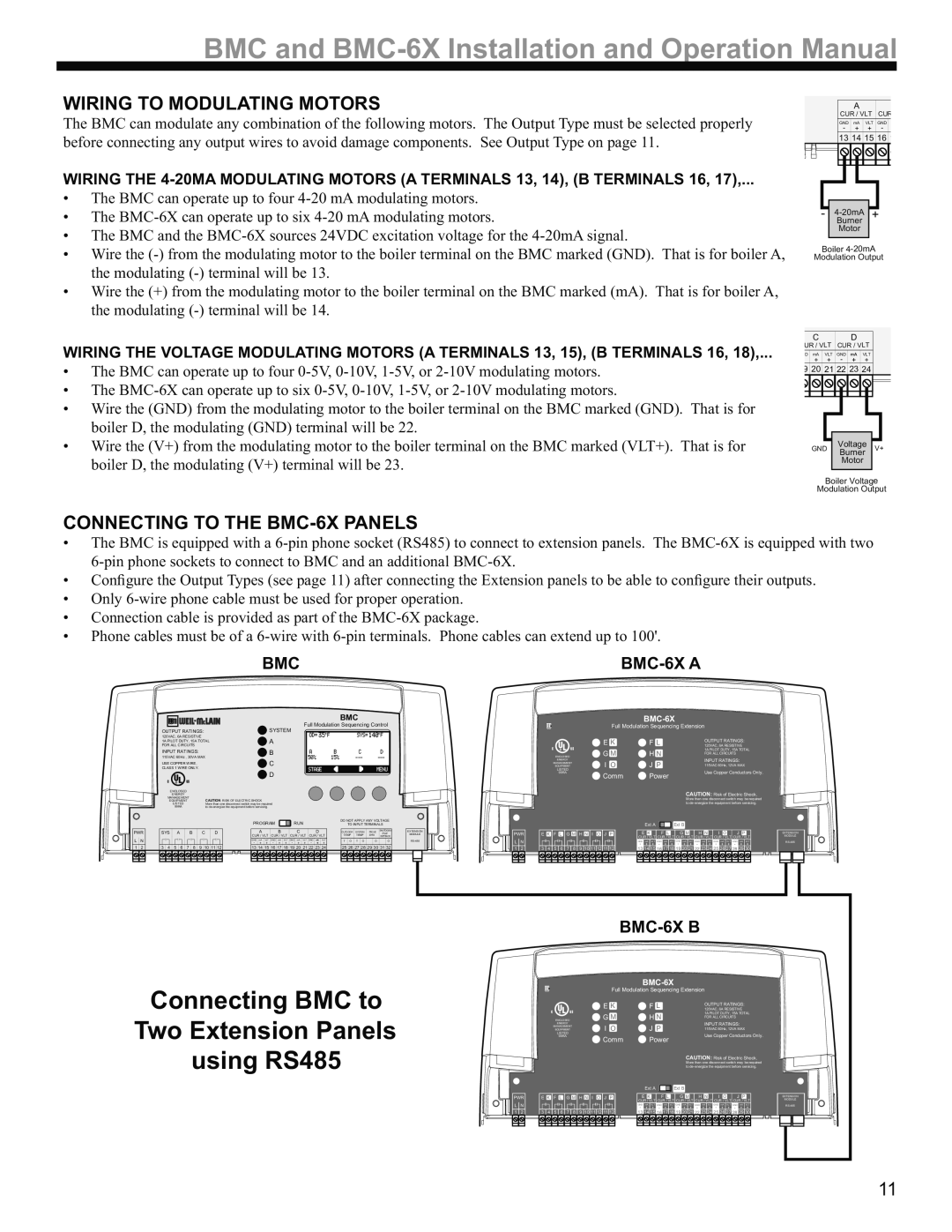
The BMC can modulate any combination of the following motors. The Output Type must be selected properly before connecting any output wires to avoid damage components. See Output Type on page 11.
|
| A |
|
|
|
| CUR / VLT | CUR | |||
| GND | mA | VLT | GND |
|
| - | + | + | - |
|
| 13 | 14 | 15 | 16 | 1 |
|
|
|
|
|
|
|
|
|
|
|
|
|
|
|
|
|
|
|
|
|
|
|
|
WIRING THE
•The BMC can operate up to four
•The
•The BMC and the
•Wire the
•Wire the (+) from the modulating motor to the boiler terminal on the BMC marked (mA). That is for boiler A, the modulating
WIRING THE VOLTAGE MODULATING MOTORS (A TERMINALS 13, 15), (B TERMINALS 16, 18),...
•The BMC can operate up to four
•The
•Wire the (GND) from the modulating motor to the boiler terminal on the BMC marked (GND). That is for boiler D, the modulating (GND) terminal will be 22.
•Wire the (V+) from the modulating motor to the boiler terminal on the BMC marked (VLT+). That is for boiler D, the modulating (V+) terminal will be 23.
-
Motor
Boiler
Modulation Output
CD
| UR / VLT |
| CUR / VLT |
|
| |||||||||||||
| D |
| mA |
| VLT |
| GND |
| mA | VLT |
|
| ||||||
|
|
| + |
| + | - |
|
| + |
| + |
|
| |||||
| 9 |
| 20 |
| 21 22 |
| 23 |
| 24 |
|
| |||||||
|
|
|
|
|
|
|
|
|
|
|
|
|
|
|
|
|
|
|
|
| Voltage |
|
| |
GND | V+ | ||||
Burner | |||||
|
|
|
| ||
|
| Motor |
|
| |
|
|
|
| ||
| Boiler Voltage | ||||
Modulation Output | |||||
CONNECTING TO THE BMC-6X PANELS
•The BMC is equipped with a
•Configure the Output Types (see page 11) after connecting the Extension panels to be able to configure their outputs.
•Only
•Connection cable is provided as part of the
•Phone cables must be of a
BMC
BMC-6X A
PWR
LN
1 2
|
|
|
|
|
|
|
|
|
|
|
|
|
|
|
|
|
|
|
|
|
|
|
|
|
|
| BMC |
|
|
|
|
|
| |||
|
|
|
|
|
|
|
|
|
|
|
|
|
|
|
|
|
| SYSTEM |
| Full Modulation Sequencing Control | ||||||||||||||||
OUTPUT RATINGS: |
|
|
|
|
|
|
|
|
|
|
|
|
|
|
|
|
|
|
|
|
|
|
| |||||||||||||
120VAC, 6A RESISTIVE |
|
|
|
|
|
|
|
|
| A |
|
|
|
|
|
|
|
|
|
|
|
|
|
|
|
|
|
| ||||||||
1A PILOT DUTY, 15A TOTAL |
|
|
|
|
|
|
|
|
|
|
|
|
|
|
|
|
|
|
|
|
|
| ||||||||||||||
FOR ALL CIRCUITS |
|
|
|
|
|
|
|
|
|
|
|
|
|
|
|
|
|
|
|
|
|
|
|
|
|
|
|
|
| |||||||
INPUT RATINGS: |
|
|
|
|
|
|
|
|
|
| B |
|
|
|
|
|
|
|
|
|
|
|
|
|
|
| ||||||||||
115VAC 60Hz , 30VA MAX |
|
|
|
|
|
|
|
|
|
|
|
|
|
|
|
|
|
|
|
|
|
|
|
| ||||||||||||
USE COPPER WIRE, |
|
|
|
|
|
|
|
|
|
| C |
|
|
|
|
|
|
|
|
|
|
|
|
|
|
|
|
|
| |||||||
CLASS 1 WIRE ONLY. |
|
|
|
|
|
|
|
|
|
|
|
|
|
|
|
|
|
|
|
|
|
|
|
|
|
|
|
|
| |||||||
|
| C |
|
| US |
|
|
|
|
|
|
|
|
|
|
|
| D |
|
|
|
|
|
|
|
|
|
|
|
|
|
|
|
|
|
|
|
|
|
|
|
|
|
|
|
|
|
|
|
|
|
|
|
|
|
|
|
|
|
|
|
|
|
|
|
|
|
|
|
|
| ||
|
| ENCLOSED |
|
|
|
|
|
|
|
|
|
|
|
|
|
|
|
|
|
|
|
|
|
|
|
|
|
|
|
|
|
|
| |||
|
|
| ENERGY |
|
|
|
|
|
|
|
|
|
|
|
|
|
|
|
|
|
|
|
|
|
|
|
|
|
|
|
|
|
|
|
| |
|
| MANAGEMENT |
|
|
|
|
|
|
|
|
|
|
|
|
|
|
|
|
|
|
|
|
|
|
|
|
|
|
|
|
|
|
| |||
|
| EQUIPMENT |
|
|
|
| CAUTION: RISK OF ELECTRIC SHOCK |
|
|
|
|
|
|
|
|
|
|
|
|
|
|
|
|
|
|
|
| |||||||||
|
|
| LISTED |
|
|
|
|
| More than one disconnect switch may be required |
|
|
|
|
|
|
|
|
|
|
|
|
|
|
|
|
|
| |||||||||
|
|
| 99RA |
|
|
|
|
| to |
|
|
|
|
|
|
|
|
|
|
|
|
|
|
|
|
|
|
| ||||||||
|
|
|
|
|
|
|
|
|
|
|
|
|
|
| PROGRAM |
|
| RUN |
|
|
| DO NOT APPLY ANY VOLTAGE | ||||||||||||||
|
|
|
|
|
|
|
|
|
|
|
|
|
|
|
|
|
|
|
|
|
| TO INPUT TERMINALS | ||||||||||||||
SYS |
| A |
| B |
| C |
|
| D |
|
| A |
|
| B |
|
| C |
|
| D |
|
| OUTDOOR | SYSTEM | PROVE | SHUTDOWN | |||||||||
|
|
|
|
|
|
|
|
|
|
|
|
|
|
| /TSAT | |||||||||||||||||||||
|
|
|
|
|
|
|
|
|
|
|
|
|
|
| CUR / VLT | CUR / VLT | CUR / VLT | CUR / VLT |
| TEMP | TEMP | /DHW | /SETBACK | |||||||||||||
|
|
|
|
|
|
|
|
|
|
|
|
|
|
| GND | mA | VLT | GND | mA | VLT | GND | mA | VLT | GND | mA | VLT |
| T | O | T | O |
| O |
| O | |
|
|
|
|
|
|
|
|
|
|
|
|
|
|
| - | + | + | - | + | + | - | + | + | - | + | + |
|
|
|
|
|
|
|
|
|
|
3 | 4 | 5 | 6 | 7 | 8 | 9 |
| 10 | 11 | 12 |
| 13 | 14 | 15 | 16 | 17 | 18 | 19 | 20 | 21 | 22 | 23 | 24 |
| 25 | 26 | 27 | 28 | 29 | 30 | 31 | 32 |
| |||
|
|
|
|
|
|
|
|
|
|
|
|
|
|
|
|
|
|
|
|
|
|
|
|
|
|
|
|
|
|
|
|
|
|
|
|
|
|
|
|
|
|
|
|
|
|
|
|
|
|
|
|
|
|
|
|
|
|
|
|
|
|
|
|
|
|
|
|
|
|
|
|
|
|
EXTENSION MODULE
BMC-6X
Full Modulation Sequencing Extension
|
| E K | F L | OUTPUT RATINGS: |
C | US | 120VAC, 6A RESISTIVE | ||
G M | H N | 1A PILOT DUTY, 15A TOTAL | ||
ENCLOSED |
| FOR ALL CIRCUITS | ||
ENERGY |
| I O | J P | INPUT RATINGS: |
MANAGEMENT | ||||
EQUIPMENT |
| 115VAC 60Hz, 12VA MAX | ||
LISTED |
|
|
| Use Copper Conductors Only. |
99RA |
| Comm | Power | |
|
|
| ||
CAUTION: Risk of Electric Shock. More than one disconnect switch may be required to
|
|
|
|
|
|
|
|
|
|
| Ext A | Ext B |
|
|
|
|
PWR | E K | F L | G M | H N I O J P |
|
|
|
| I | O | J P | |||||
|
|
|
|
|
|
|
|
|
|
|
|
|
| CUR / VLT CUR / VLT | ||
L | N |
|
|
|
|
|
|
|
| GND | GND | GND | GND | GND | mA | VLT GND mA VLT |
1 | 2 | 3 | 4 | 5 | 6 | 7 | 8 | 9 | 10 11 12 11 12 | 13 14 15 16 17 18 19 20 21 22 23 24 25 26 27 2816 29 30 | ||||||
EXTENSION |
MODULE |
Connecting BMC to Two Extension Panels using RS485
Full Modulation Sequencing Extension
|
| E K | F L | OUTPUT RATINGS: |
C | US | 120VAC, 6A RESISTIVE | ||
G M | H N | 1A PILOT DUTY, 15A TOTAL | ||
| ENCLOSED | FOR ALL CIRCUITS | ||
| ENERGY | I O | J P | INPUT RATINGS: |
| MANAGEMENT | |||
| EQUIPMENT | 115VAC 60Hz, 12VA MAX | ||
| LISTED |
|
| Use Copper Conductors Only. |
| 99RA | Comm | Power | |
|
|
| ||
|
|
|
| CAUTION: Risk of Electric Shock. |
|
|
|
| More than one disconnect switch may be required |
|
|
|
| to |
|
|
|
|
|
|
|
|
|
|
| Ext A | Ext B |
|
|
|
|
PWR | E K | F L | G M | H N I O J P |
|
|
|
| I | O | J P | |||||
|
|
|
|
|
|
|
|
|
|
|
|
|
| CUR / VLT CUR / VLT | ||
L | N |
|
|
|
|
|
|
|
| GND | GND | GND | GND | GND | mA | VLT GND mA VLT |
1 | 2 | 3 | 4 | 5 | 6 | 7 | 8 | 9 | 10 11 12 11 12 | 13 14 15 16 17 18 19 20 21 22 23 24 25 26 27 2816 29 30 | ||||||
EXTENSION |
MODULE |
11