BMC and
BMC LAYOUT
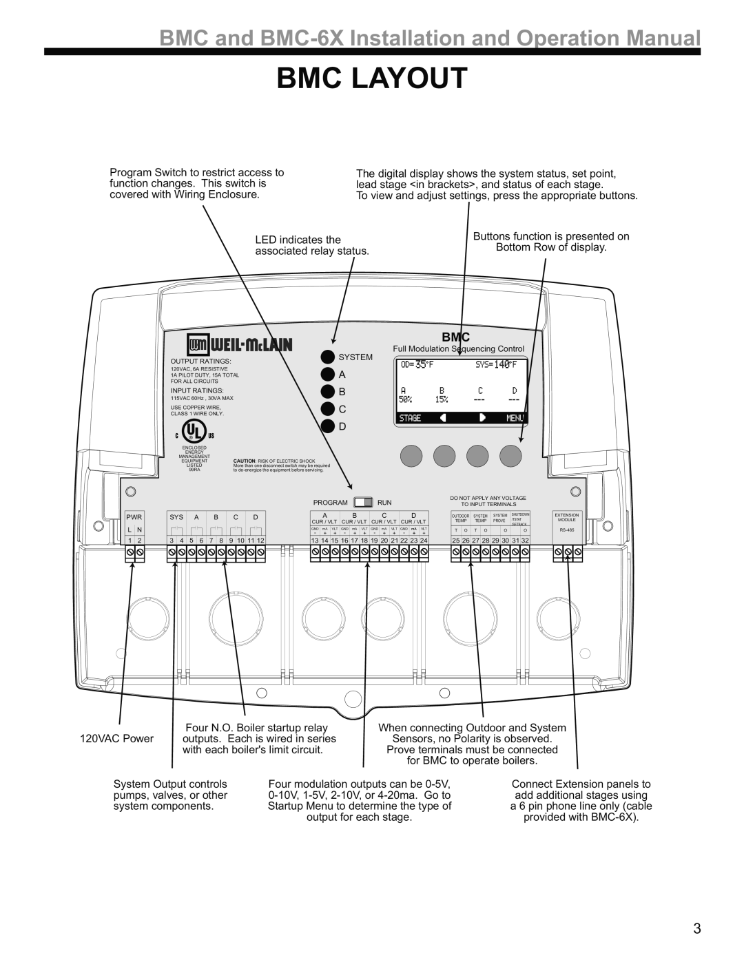
Program Switch to restrict access to function changes. This switch is covered with Wiring Enclosure.
The digital display shows the system status, set point, lead stage <in brackets>, and status of each stage.
To view and adjust settings, press the appropriate buttons.
LED indicates the | Buttons function is presented on | |
Bottom Row of display. | ||
associated relay status. | ||
|
OUTPUT RATINGS:
120VAC, 6A RESISTIVE
1A PILOT DUTY, 15A TOTAL FOR ALL CIRCUITS
INPUT RATINGS:
115VAC 60Hz , 30VA MAX
USE COPPER WIRE, CLASS 1 WIRE ONLY.
C ![]()
![]() US
US
BMC
Full Modulation Sequencing Control
SYSTEM
![]() A
A
B | |||
C | |||
|
| ||
D |
|
|
PWR
LN
1 2
ENCLOSED |
|
ENERGY |
|
MANAGEMENT | CAUTION: RISK OF ELECTRIC SHOCK |
EQUIPMENT | |
LISTED | More than one disconnect switch may be required |
99RA | to |
|
|
|
|
|
|
|
|
|
|
|
|
|
|
|
|
|
|
|
|
|
|
| PROGRAM |
|
|
| RUN |
|
|
| DO NOT APPLY ANY VOLTAGE | |||||||||||||
|
|
|
|
|
|
|
|
|
|
|
|
|
|
|
|
|
|
|
|
|
|
|
|
|
|
|
|
|
|
| TO INPUT TERMINALS | |||||||||||||
|
|
|
|
|
|
|
|
|
|
|
|
|
|
|
|
|
|
|
|
|
|
|
|
|
|
|
|
|
|
|
|
|
|
|
|
|
|
|
|
|
|
|
|
|
SYS |
| A |
|
|
|
| B |
|
| C |
| D |
|
| A |
|
| B |
|
| C |
|
| D |
|
| OUTDOOR | SYSTEM | SYSTEM | SHUTDOWN | ||||||||||||||
|
|
|
|
|
|
|
|
|
|
|
|
|
|
|
|
|
| /TSTAT | ||||||||||||||||||||||||||
|
|
|
|
|
|
|
|
| CUR / VLT | CUR / VLT | CUR / VLT | CUR / VLT |
| TEMP | TEMP | PROVE | ||||||||||||||||||||||||||||
|
|
|
|
|
|
|
|
|
|
|
|
|
|
|
|
|
|
|
|
|
|
|
|
|
|
|
|
|
| /SETBACK | ||||||||||||||
|
|
|
|
|
|
|
|
|
|
|
|
|
|
|
|
|
|
|
|
|
|
| GND | mA | VLT | GND | mA | VLT | GND | mA | VLT | GND | mA | VLT |
| T | O | T | O |
| O |
| O | |
|
|
|
|
|
|
|
|
|
|
|
|
|
|
|
|
|
|
|
|
|
|
| - | + | + | - | + | + | - | + | + | - | + | + |
|
|
| |||||||
|
|
|
|
|
|
|
|
|
|
|
|
|
|
|
|
|
|
|
|
|
|
|
|
|
|
|
|
|
|
|
| |||||||||||||
3 | 4 | 5 | 6 | 7 |
| 8 | 9 |
| 10 | 11 | 12 |
| 13 | 14 | 15 | 16 | 17 | 18 | 19 | 20 | 21 | 22 | 23 | 24 |
| 25 | 26 | 27 | 28 | 29 | 30 | 31 | 32 | |||||||||||
|
|
|
|
|
|
|
|
|
|
|
|
|
|
|
|
|
|
|
|
|
|
|
|
|
|
|
|
|
|
|
|
|
|
|
|
|
|
|
|
|
|
|
|
|
|
|
|
|
|
|
|
|
|
|
|
|
|
|
|
|
|
|
|
|
|
|
|
|
|
|
|
|
|
|
|
|
|
|
|
|
|
|
|
|
|
|
|
|
|
EXTENSION MODULE
120VAC Power | Four N.O. Boiler startup relay | When connecting Outdoor and System | ||
outputs. Each is wired in series | Sensors, no Polarity is observed. | |||
| with each boiler's limit circuit. | Prove terminals must be connected | ||
|
|
| for BMC to operate boilers. | |
System Output controls | Four modulation outputs can be | Connect Extension panels to | ||
pumps, valves, or other | add additional stages using | |||
system components. | Startup Menu to determine the type of | a 6 pin phone line only (cable | ||
|
| output for each stage. | provided with | |
3