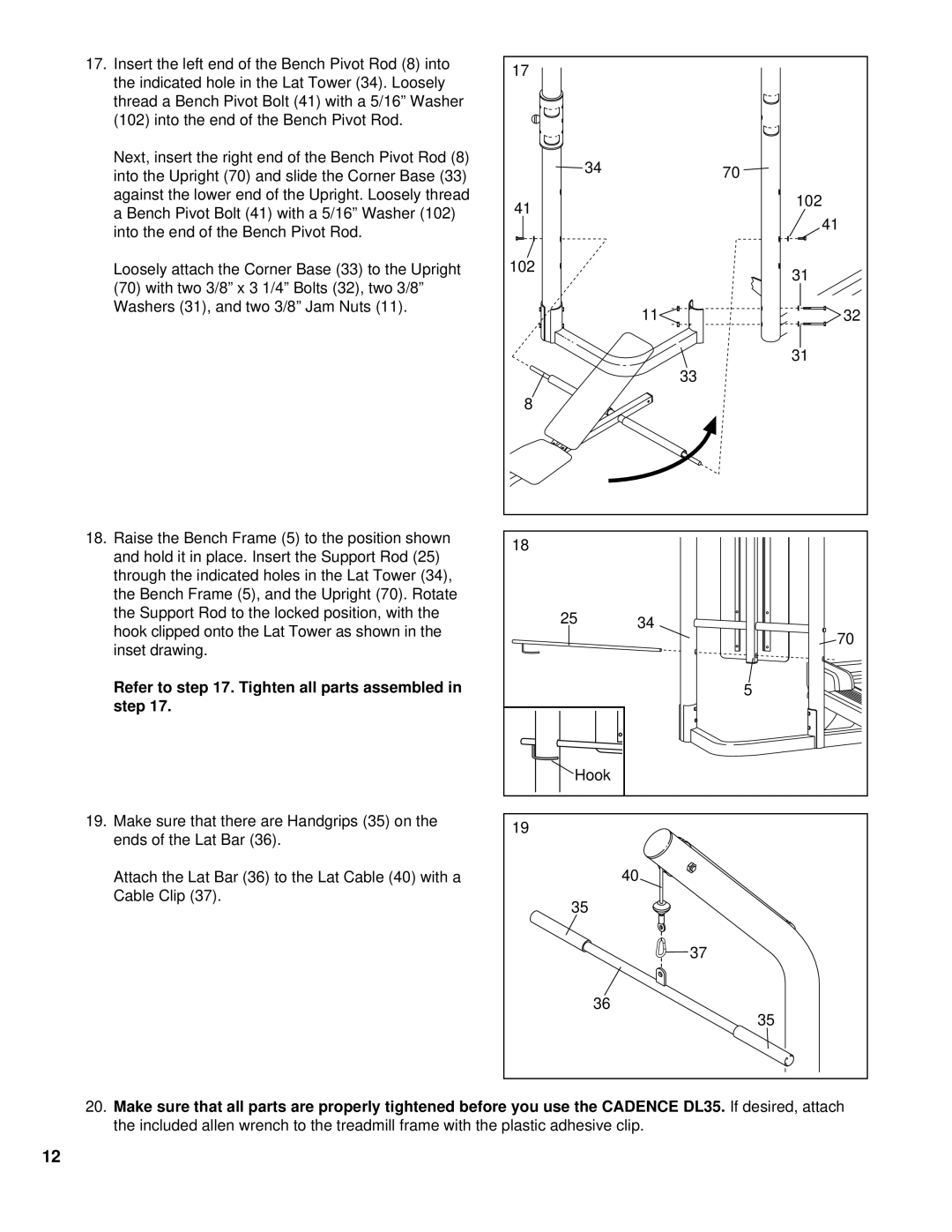
17.Insert the left end of the Bench Pivot Rod (8) into the indicated hole in the Lat Tower (34). Loosely thread a Bench Pivot Bolt (41) with a 5/16” Washer (102) into the end of the Bench Pivot Rod.
Next, insert the right end of the Bench Pivot Rod (8) into the Upright (70) and slide the Corner Base (33) against the lower end of the Upright. Loosely thread a Bench Pivot Bolt (41) with a 5/16” Washer (102) into the end of the Bench Pivot Rod.
Loosely attach the Corner Base (33) to the Upright
(70)with two 3/8” x 3 1/4” Bolts (32), two 3/8” Washers (31), and two 3/8” Jam Nuts (11).
18.Raise the Bench Frame (5) to the position shown and hold it in place. Insert the Support Rod (25) through the indicated holes in the Lat Tower (34), the Bench Frame (5), and the Upright (70). Rotate the Support Rod to the locked position, with the hook clipped onto the Lat Tower as shown in the inset drawing.
Refer to step 17. Tighten all parts assembled in step 17.
19.Make sure that there are Handgrips (35) on the ends of the Lat Bar (36).
Attach the Lat Bar (36) to the Lat Cable (40) with a Cable Clip (37).
17 |
|
|
34 |
| 70 |
|
| |
41 |
| 102 |
| 41 | |
|
| |
102 |
| 31 |
|
| |
| 11 | 32 |
|
| 31 |
|
| 33 |
8 |
|
|
18 |
|
|
25 | 34 |
|
| 70 | |
|
| |
|
| 5 |
Hook |
|
|
19 |
|
|
| 40 |
|
35 |
|
|
|
| 37 |
36 |
| 35 |
|
|
20.Make sure that all parts are properly tightened before you use the CADENCE DL35. If desired, attach the included allen wrench to the treadmill frame with the plastic adhesive clip.
12
