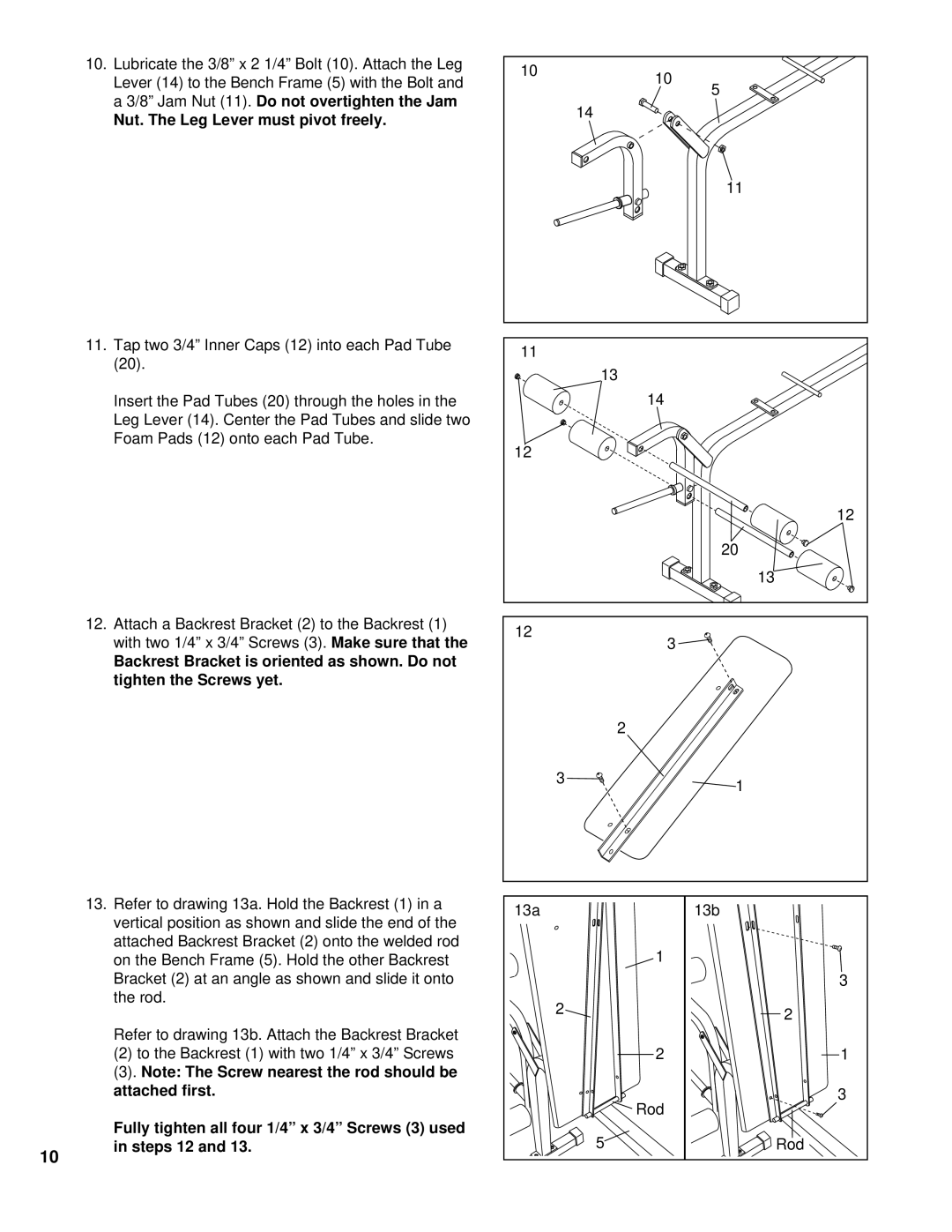
10.Lubricate the 3/8” x 2 1/4” Bolt (10). Attach the Leg Lever (14) to the Bench Frame (5) with the Bolt and a 3/8” Jam Nut (11). Do not overtighten the Jam
Nut. The Leg Lever must pivot freely.
11.Tap two 3/4” Inner Caps (12) into each Pad Tube (20).
Insert the Pad Tubes (20) through the holes in the Leg Lever (14). Center the Pad Tubes and slide two Foam Pads (12) onto each Pad Tube.
12.Attach a Backrest Bracket (2) to the Backrest (1) with two 1/4” x 3/4” Screws (3). Make sure that the
Backrest Bracket is oriented as shown. Do not tighten the Screws yet.
13.Refer to drawing 13a. Hold the Backrest (1) in a vertical position as shown and slide the end of the attached Backrest Bracket (2) onto the welded rod on the Bench Frame (5). Hold the other Backrest Bracket (2) at an angle as shown and slide it onto the rod.
Refer to drawing 13b. Attach the Backrest Bracket
(2)to the Backrest (1) with two 1/4” x 3/4” Screws
(3).Note: The Screw nearest the rod should be attached first.
10 | 10 |
|
| 5 | |
|
| |
| 14 |
|
|
| 11 |
11 |
|
|
| 13 |
|
| 14 |
|
12 |
|
|
|
| 12 |
|
| 20 |
|
| 13 |
12 | 3 |
|
|
| |
| 2 |
|
| 3 | 1 |
|
| |
13a |
| 13b |
| 1 |
|
|
| 3 |
| 2 | 2 |
|
| |
| 2 | 1 |
| Rod | 3 |
|
|
10
Fully tighten all four 1/4” x 3/4” Screws (3) used in steps 12 and 13.
5 | Rod |
