Instruction Leaflet
30-471 (E)
Page 6
Type “RO” Robonic II Automatic Transfer Switch
A complete line rated from 150 amperes through 1000 amperes at 600 volts Ac or at 250 volts Dc.
The transfer mechanism consists of the transfer motor, a gear train and two breaker operating cams.
Type “PRO” Robonic II Automatic Transfer Switch
Rated 1200 amperes through 3000 amperes at 600 volts Ac or 250 volts Dc.
The transfer mechanism consists of a transfer motor, a gear train and two breaker operating cams.
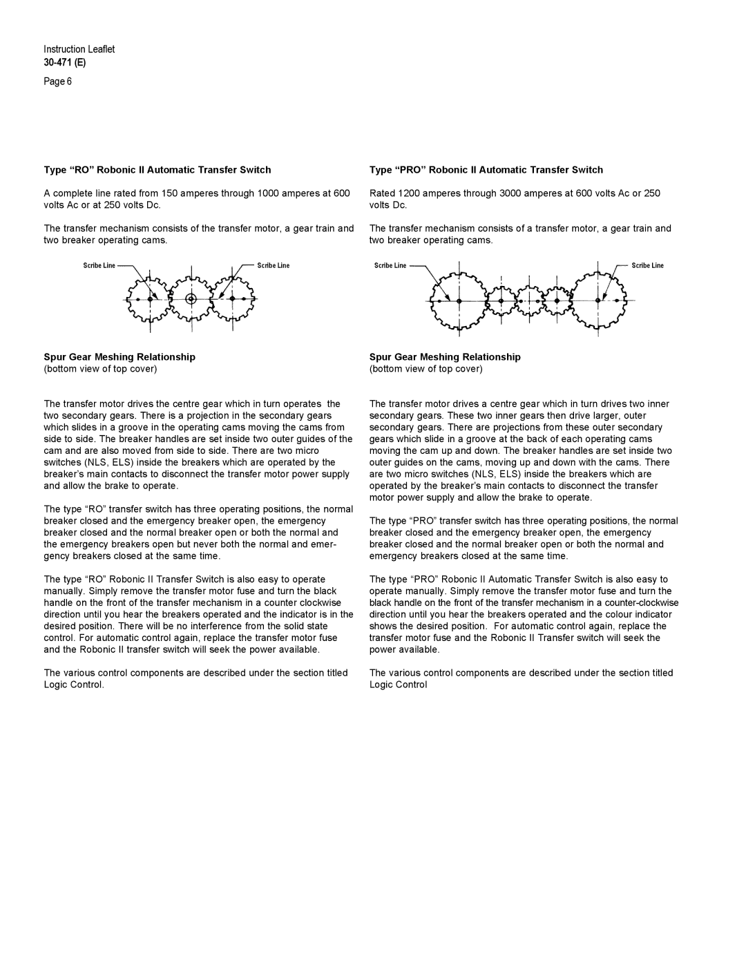
Scribe Line | Scribe Line | Scribe Line | Scribe Line |
Spur Gear Meshing Relationship | Spur Gear Meshing Relationship |
(bottom view of top cover) | (bottom view of top cover) |
The transfer motor drives the centre gear which in turn operates the two secondary gears. There is a projection in the secondary gears which slides in a groove in the operating cams moving the cams from side to side. The breaker handles are set inside two outer guides of the cam and are also moved from side to side. There are two micro switches (NLS, ELS) inside the breakers which are operated by the breaker’s main contacts to disconnect the transfer motor power supply and allow the brake to operate.
The type “RO” transfer switch has three operating positions, the normal breaker closed and the emergency breaker open, the emergency breaker closed and the normal breaker open or both the normal and the emergency breakers open but never both the normal and emer- gency breakers closed at the same time.
The type “RO” Robonic II Transfer Switch is also easy to operate manually. Simply remove the transfer motor fuse and turn the black handle on the front of the transfer mechanism in a counter clockwise direction until you hear the breakers operated and the indicator is in the desired position. There will be no interference from the solid state control. For automatic control again, replace the transfer motor fuse and the Robonic II transfer switch will seek the power available.
The various control components are described under the section titled Logic Control.
The transfer motor drives a centre gear which in turn drives two inner secondary gears. These two inner gears then drive larger, outer secondary gears. There are projections from these outer secondary gears which slide in a groove at the back of each operating cams moving the cam up and down. The breaker handles are set inside two outer guides on the cams, moving up and down with the cams. There are two micro switches (NLS, ELS) inside the breakers which are operated by the breaker’s main contacts to disconnect the transfer motor power supply and allow the brake to operate.
The type “PRO” transfer switch has three operating positions, the normal breaker closed and the emergency breaker open, the emergency breaker closed and the normal breaker open or both the normal and emergency breakers closed at the same time.
The type “PRO” Robonic II Automatic Transfer Switch is also easy to operate manually. Simply remove the transfer motor fuse and turn the black handle on the front of the transfer mechanism in a
The various control components are described under the section titled Logic Control