Electrical connection
. *
Electrical Shock Hazard
: 2: :! Turn power supply off before
.:.:.:
.i’l’i; supp,y cordm
‘:.!. Plug into a grounded outlet. j i ! Failure to follow these
; ; .: instructions can result in
:
: : death, fire, or electrical shock.
: :
1 . Turn power supply off.
2 . Remove | screw and | |
terminal block | cover. |
|
external |
|
|
ground |
|
|
connecto- |
| $o$ |
I | terminal | I / |
tab | block cover |
|
|
| |
x
Figure 6
3 . Attach 3/4”
strain relief.
rear
power
strain relief~o~$lY (outside
dryer)
Figure 7
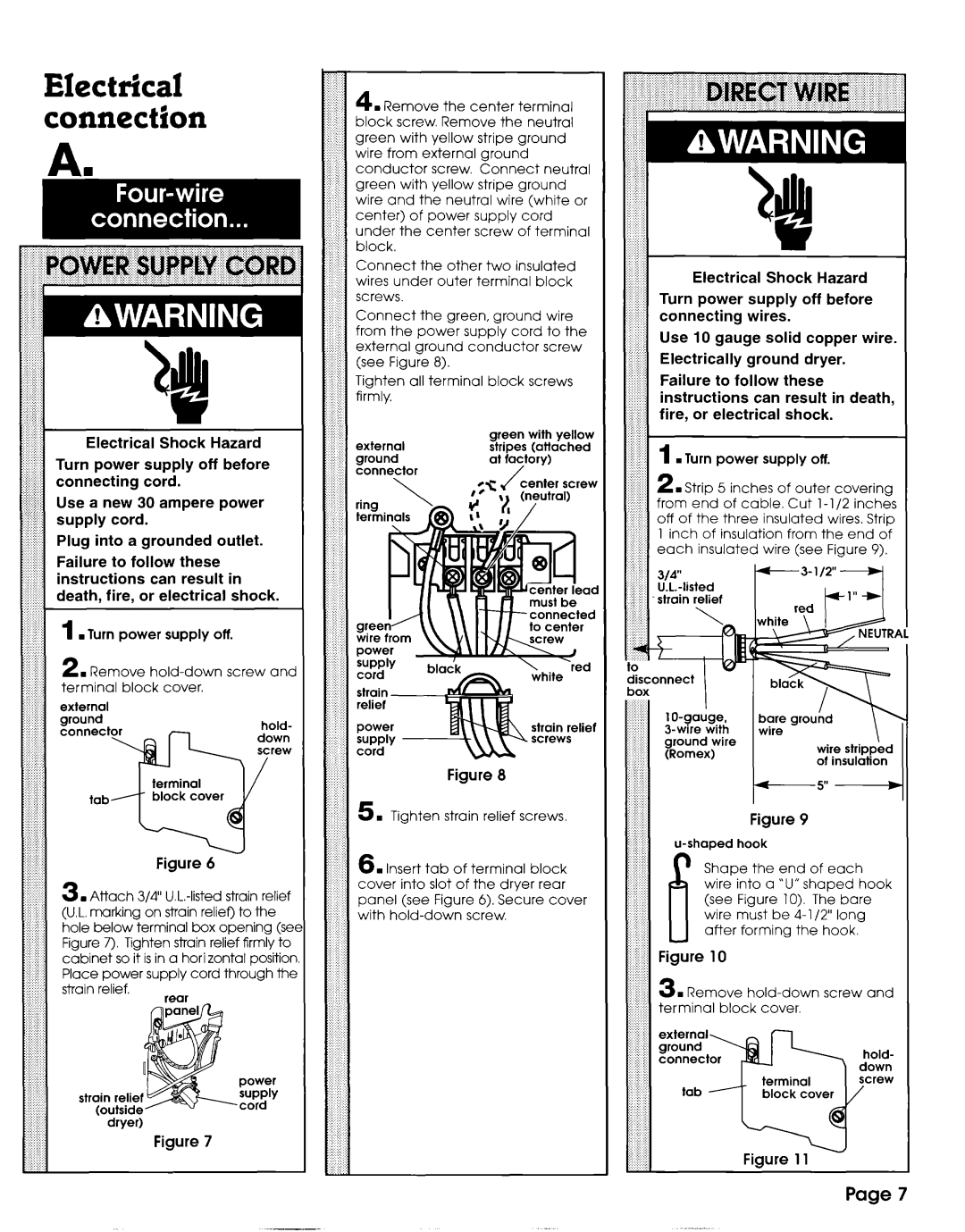
4 . Remove the center terminal block screw. Remove the neutral green with yellow stripe ground wire from external ground conductor screw. Connect neutral green with yellow stripe ground wire and the neutral wire (white or center) of power supply cord under the center screw of terminal block.
Connect the other two insulated wires under outer terminal block screws.
Connect the green, ground wire from the power supply cord to the external ground conductor screw (see Figure 8).
Tighten all terminal block screws firmly.
external | green | with yellow |
stripes | (attached | |
ground | at factory) | |
connector | / |
|
termi
green ‘/ wire from
Figure 8
5 . Tighten strain relief screws
6 . Insert tab of terminal block cover into slot of the dryer rear panel (see Figure 6). Secure cover with
::,.:::..
.: ah
::1 *
Electrical Shock Hazard
Turn power supply off before connecting wires.
Use 10 gauge solid copper wire. Electrically ground dryer.
Failure to follow these instructions can result in death, fire, or electrical shock.
. Turn power supply off.
ion from the end of each insulated wire (see Figure 9).
red
tis;onnect
II
(Romex)wire stripped ot insulation
t
Figure 9
P Shape the end of each wire into a ‘U” shaped hook (see Figure 10). The bare wire must be
Figure 10
3 . Remove
hold- down screw
/
Figure 11
Page 7