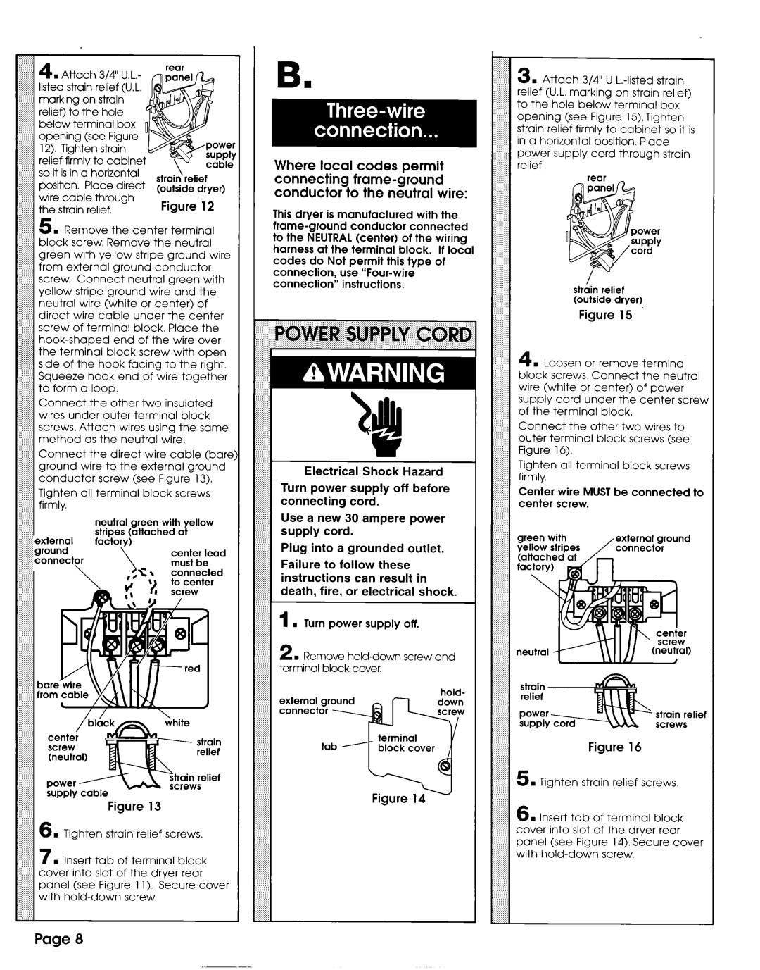
4 . Attach 3/4” U.L.- listed strain relief (U.L. marking on strain relief) to the hole below terminal box opening (see Figure 12). Tighten strain relief firmly to cabinet so it is in a horizontal position. Place direct wire cable through the strain relief.
(outside dryer)
Figure 12
B.
Where local codes permit connecting
This dryer is manufactured with the
3 . Attach 3/4”
,i$ 5 . Remove the center terminal
..!,!!,: block screw, Remove the neutral
.i! - ‘!: from external ground conductor
j ;,; screw. Connect neutral green with
.. !: yellow stripe ground wire and the ;.;.j..; neutral wire (white or center) of $j ! direct wire cable under the center $I:‘:.:screw of terminal block. Place the
Z$.iij Connect the other two insulated ;:;si..iwires under outer terminal block
I:i. screws. Attach wires using the same $ ;.I method as the neutral wire.
...j;..$;; Connect the direct wire cable (bare f; :; ground wire to the external ground
:1 conductor screw (see Figure 13).
.: i. Tighten all terminal block screws
:,; j : firmly.
| neutral | green with | yellow |
~; zjexternal | stripes | (attached | at |
factory) |
|
|
connection” instructions.
Electrical Shock Hazard
Turn power supply off before
connecting cord.
rounded outlet.
1 . Turn power supply off.
2 . Remove
hold-
external ground
strhin relief (outside dryer)
Figure 15
#i: 4 . Loosen or remove terminal
:: block screws. Connect the neutral
::
: : wire (white or center) of power
:1 supply cord under the center screw :.j
:; ,; of the terminal block.
’,: : Connect the other two wires to
:: :: outer terminal block screws (see
:: :j: : Figure 16).
:: : Tighten all terminal block screws
j : firmly,
:: :: Center wire MUST be connected to
:: c center screw.
::..::
: : |
|
: : | external ground |
: : | |
: : |
|
: : |
|
:c
::
: :
! :
strain relief screws
Figure 16
Figure 13
strain relief screws.
. Insert tab of terminal block :.i :I. cover into slot of the dryer rear
i’ ‘$. panel (see Figure 1 1). Secure
i.5 . Tighten strain relief screws.
6 . Insert tab of terminal block
:cover into slot of the dryer rear
panel (see Figure 14). Secure cover
:: with
::
::::: ::
:
Page 8