Manuals
/
Whirlpool
/
Kitchen Appliance
/
Range
Whirlpool
EDP/EDN
warranty
Ignition Fault Tree
Models:
EDP/EDN
1
24
36
36
Download
36 pages
52.37 Kb
21
22
23
24
25
26
27
28
EDP/EDN Wiring Diagram
Power UP Fault Tree
10A. Delayed ignition
7J. Cleaning the Boiler Coil
Boiler Temperature
To read or change mode
Page 24
Image 24
Page 24
LAARS HEATING SYSTEMS
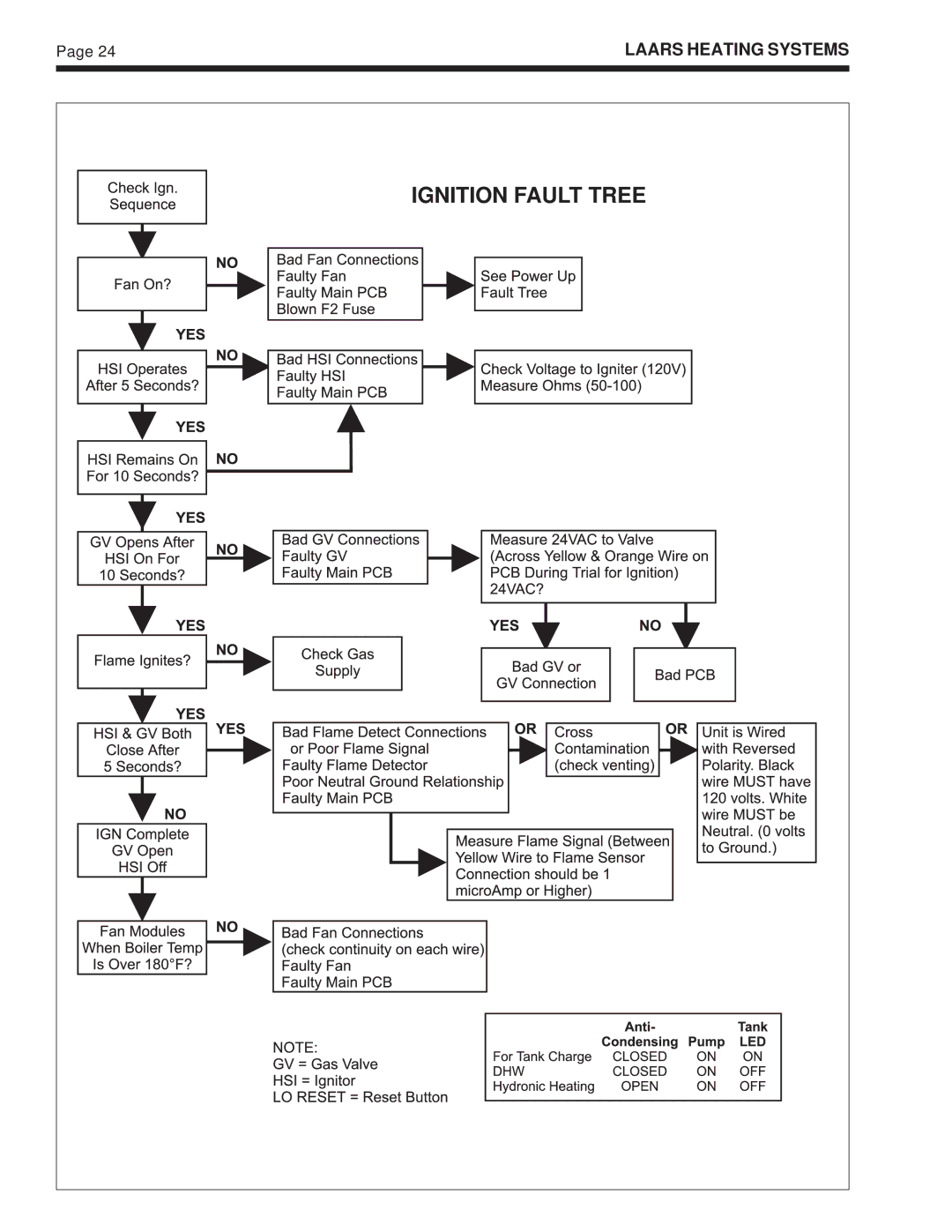
IGNITION FAULT TREE
Page 23
Page 25
Page 24
Image 24
Page 23
Page 25
Contents
Endurance
Table of Contents
General Information
1A. Introduction
1B. Codes and Standards
Venting Options
Endurance
Laars Heating Systems
2E. Air Source For Combustion when not direct vented
For Appliances Certified as Direct Vent
2F. Connecting Special Gas Vent to the Appliance
2G. Securing Special Gas Vent
3A. Gas Piping
3B. Domestic Water Piping EBP only
Length Capacity of Pipe
Hydronic Heat Piping
4A. Hydronic Piping
Hydronic Piping EDP/EBP with Zone Valves
Hydronic Piping EBP/EDP for Systems Zoned with Circulators
Electrical Connections
4C. Water Quality and Treatment
Multiple Zones with Circulators and Room Thermostats
For Your Safety Read Before Operating
Fermeture DE L’ALIMENTATION EN GAZ
To read or change mode
Boiler Start Up
6A. Common Vent Test
6B. Filling the System
6C. Firing Burner
Maintenance and Component Description
7E. Ignitor / Flame Sensor Assembly
7J. Cleaning the Boiler Coil
7F. Transformer
7G. Blower
Servicing
8A. Sequence of Operation
8B. Trouble Shooting Fault Codes
8B-1. Fault Code Identification
Power UP Fault Tree
Ignition Fault Tree
Space Heating
Domestic HOT Water
Boiler Temperature
Poor flame sensor signal The boiler control
EDP/EDN Wiring Diagram
EBP Wiring Diagram
Symptom Evaluations
9A. Gas Valve Calibration offset adjustment
10A. Delayed ignition
Gas Valve Calibration
10B. Short Cycling
10C. Noisy Operation
10D. Insufficient Hot Water EBP only
10E. High Gas Consumption
Parts Identification
Model EDP/EDN
Model EBP
Boiler Drain
Box Lynnfield, MA Phone Fax
Top
Page
Image
Contents