Page 8 | LAARS HEATING SYSTEMS |
|
|
|
|
Figure 10. Special Gas Vent Connection.
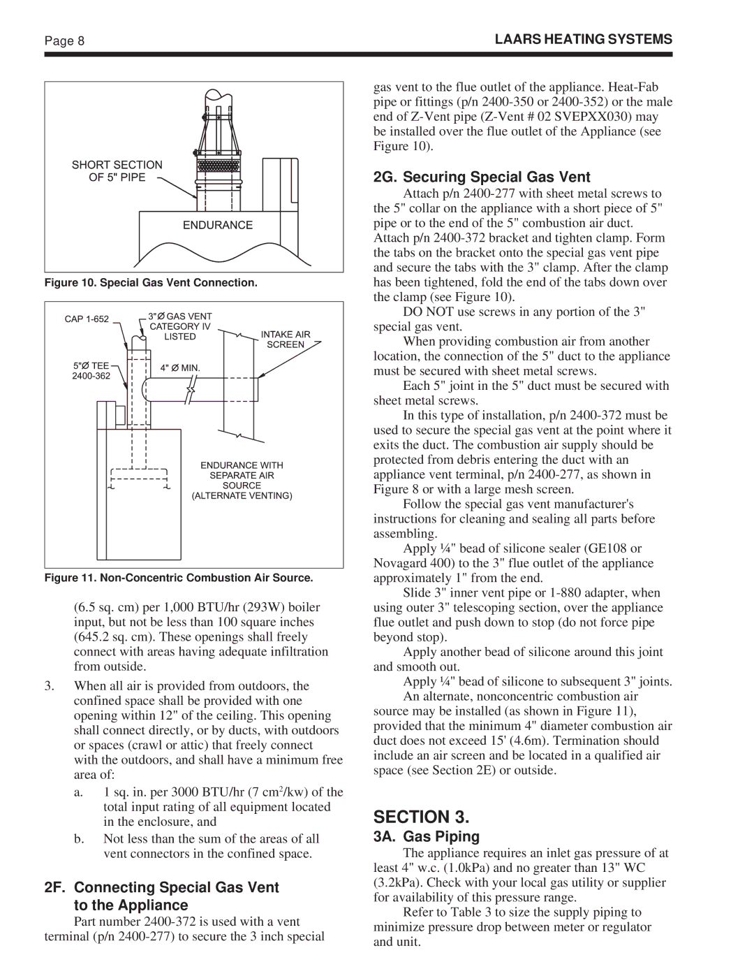
Figure 11. Non-Concentric Combustion Air Source.
(6.5 sq. cm) per 1,000 BTU/hr (293W) boiler input, but not be less than 100 square inches (645.2 sq. cm). These openings shall freely connect with areas having adequate infiltration from outside.
3.When all air is provided from outdoors, the confined space shall be provided with one opening within 12" of the ceiling. This opening shall connect directly, or by ducts, with outdoors or spaces (crawl or attic) that freely connect with the outdoors, and shall have a minimum free area of:
a.1 sq. in. per 3000 BTU/hr (7 cm2/kw) of the total input rating of all equipment located in the enclosure, and
b.Not less than the sum of the areas of all vent connectors in the confined space.
2F. Connecting Special Gas Vent to the Appliance
Part number
gas vent to the flue outlet of the appliance.
2G. Securing Special Gas Vent
Attach p/n
Attach p/n
DO NOT use screws in any portion of the 3" special gas vent.
When providing combustion air from another location, the connection of the 5" duct to the appliance must be secured with sheet metal screws.
Each 5" joint in the 5" duct must be secured with sheet metal screws.
In this type of installation, p/n
Follow the special gas vent manufacturer's instructions for cleaning and sealing all parts before assembling.
Apply ¼" bead of silicone sealer (GE108 or Novagard 400) to the 3" flue outlet of the appliance approximately 1" from the end.
Slide 3" inner vent pipe or
Apply another bead of silicone around this joint and smooth out.
Apply ¼" bead of silicone to subsequent 3" joints. An alternate, nonconcentric combustion air
source may be installed (as shown in Figure 11), provided that the minimum 4" diameter combustion air duct does not exceed 15' (4.6m). Termination should include an air screen and be located in a qualified air space (see Section 2E) or outside.
SECTION 3.
3A. Gas Piping
The appliance requires an inlet gas pressure of at least 4" w.c. (1.0kPa) and no greater than 13" WC (3.2kPa). Check with your local gas utility or supplier for availability of this pressure range.
Refer to Table 3 to size the supply piping to minimize pressure drop between meter or regulator and unit.