Determine vent length and elbows needed for best drying performance
Use the Vent system chart below to determine type of vent material and hood combinations acceptable to use.
NOTE: Do not use vent runs longer than those specified in the Vent system chart. Exhaust systems longer than those specified will:
Shorten the life of the dryer.
Reduce performance, resulting in longer drying times and increased energy usage.
The Vent system chart provides venting requirements that will help to achieve the best drying performance.
Vent system chart
NOTE: Side exhaust installations add a 90º turn inside the dryer. To determine maximum exhaust length, add one 90º turn to the chart.
Number of | Type of Vent | Box or | Angled | |
90º turns |
| Louvered | hoods | |
or elbows |
| hoods |
| |
|
|
|
|
|
0 | Rigid metal | 37 | ft (11.3 m) | 35 ft (10.7 m) |
|
|
|
|
|
1 | Rigid metal | 32 | ft (9.7 m) | 27 ft (8.2 m) |
|
|
|
|
|
2 | Rigid metal | 24 | ft (7.3 m) | 19 ft (5.8 m) |
InstallVentSystem
1.Install exhaust hood. Use caulking compound to seal exterior wall opening around exhaust hood.
2.Connect vent to exhaust hood. Vent must fit inside exhaust hood. Secure vent to exhaust hood with 4" (102 mm) clamp.
3.Run vent to dryer location. Use the straightest path possible. See “Determine vent path” in “Plan Vent System.” Avoid 90º turns. Use clamps to seal all joints. Do not use duct tape, screws, or other fastening devices that extend into the interior of the vent to secure the vent, because they can catch lint.
LevelWasher/Dryer
Properly leveling your washer/dryer avoids excessive noise and vibration.
1.Check the levelness of the washer/dryer by placing a level on the top edge of the washer, first side to side, then front to back.
2.If the washer/dryer is not level, prop up the front with the wood block and adjust the feet up or down as necessary. Remove wood block.
3.Tilt the washer/dryer forward until the rear of the washer/dryer is at least 4" (102 mm) off the floor. You may hear the self- adjusting rear feet click into place. Lower the washer/dryer to the floor. Check the levelness of the washer/dryer with a level as shown above.
If washer/dryer will not level, recheck rear leveling legs for free movement as described in the “Install Leveling Legs” section. Repeat until the washer/dryer is level.
NOTE: It may be necessary to level the washer/dryer again after it is moved into its final location.
4.After the washer/dryer is in its final location and is level, use an adjustable or
If the nuts are not tight against the washer cabinet, the washer/dryer may vibrate.
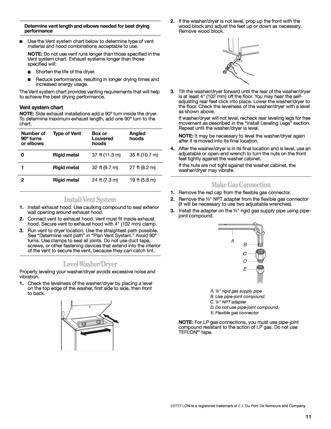
MakeGasConnection
1.Remove the red cap from the flexible gas connector.
2.Remove the ½" NPT adapter from the flexible gas connector (it will be necessary to use two adjustable wrenches).
3.Install the adapter on the ½" rigid gas supply pipe using pipe- joint compound.
AB ![]()
![]()
C ![]()
![]() D
D ![]() E
E ![]()
![]()
A.½" rigid gas supply pipe
B.Use
C.½" NPT adapter
D.Do not use
E.Flexible gas connector
NOTE: For LP gas connections, you must use
†®TEFLON is a registered trademark of E.I. Du Pont De Nemours and Company.
11