Planning the Installation
Planning the Makeup Air Switch Duct installation
This makeup air kit can only be used with vented range hoods. The makeup air kit must match the vent transition size for your range hood.
Planning the Motorized Damper installation
Planning the installation first requires selecting the most appropriate installation approach. The following illustrations offer suggestions for the most effective installation approach by considering a few important factors.
Typical Installations
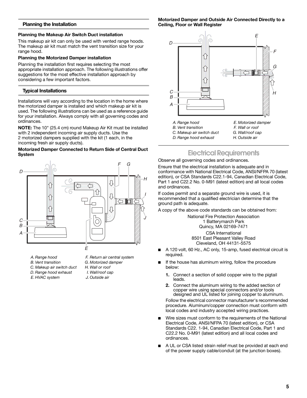
Installations will vary according to the location in the home where the motorized damper is installed and which makeup air kit is used. The following illustrations can be used as a reference guide for your installation. Always comply with all governing codes and ordinances.
NOTE: The 10" (25.4 cm) round Makeup Air Kit must be installed with 2 independent incoming air supply ducts. Use the
2 motorized dampers supplied with the kit (1 each, in the incoming fresh air supply ducts).
Motorized Damper Connected to Return Side of Central Duct System
F | G |
D |
|
| H |
| I |
C | J |
| |
B |
|
A |
|
E |
|
A. Range hood | F. Return air central system |
B. Vent transition | G. Motorized damper |
C. Makeup air switch duct | H. Wall or roof |
D. Range hood exhaust | I. Wall/roof cap |
E. HVAC system | J. Outside air |
Motorized Damper and Outside Air Connected Directly to a Ceiling, Floor or Wall Register
| E |
D |
|
| F |
| G |
C | H |
B |
|
A |
|
A. Range hood | E. Motorized damper |
B. Vent transition | F. Wall or roof |
C. Makeup air switch duct | G. Wall/roof cap |
D. Range hood exhaust | H. Outside air |
Electrical Requirements
Observe all governing codes and ordinances.
Ensure that the electrical installation is adequate and in conformance with National Electrical Code, ANSI/NFPA 70 (latest edition), or CSA Standards
If codes permit and a separate ground wire is used, it is recommended that a qualified electrician determine that the ground path is adequate.
A copy of the above code standards can be obtained from:
National Fire Protection Association
1 Batterymarch Park
Quincy, MA
CSA International
8501 East Pleasant Valley Road
Cleveland, OH
■A 120 volt, 60 Hz., AC only,
■If the house has aluminum wiring, follow the procedure below:
1.Connect a section of solid copper wire to the pigtail leads.
2.Connect the aluminum wiring to the added section of copper wire using special connectors and/or tools designed and UL listed for joining copper to aluminum.
Follow the electrical connector manufacturer's recommended procedure. Aluminum/copper connection must conform with local codes and industry accepted wiring practices.
■Wire sizes must conform to the requirements of the National Electrical Code, ANSI/NFPA 70 (latest edition), or CSA Standards C22.
■A UL or CSA listed strain relief must be provided at each end of the power supply cable/conduit (at the junction boxes).
5