Guided’utilisationetd’entretien
W10054070A
Table of Contents
Índice
Dryer Safety
Your safety and the safety of others are very important
LocationRequirements
Installation Instructions
ToolsandParts
Electrical Requirements-U.S.A.Only
Mobile home Additional installation requirements
Mobile home installations require
It is your responsibility
If connecting by direct wire
ElectricalRequirements-CanadaOnly
Style 1 Power supply cord strain relief
Power Supply Cord Direct Wire
Install strain relief
ElectricalConnection-U.S.A.Only
Wire connection Power supply cord
Style 2 Direct wire strain relief
Wire connection Direct Wire
Remove center silver-colored terminal block screw
BDE CG F
Optional 3-wire connection
If this is a new vent system Vent material
If using an existing vent system
VentingRequirements
PlanVentSystem
Alternate installations for close clearances
Special provisions for mobile home installations
Determine vent path
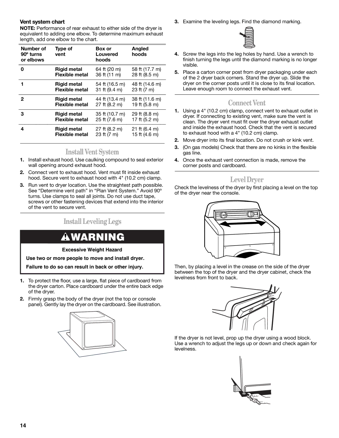
Vent system chart
Install VentSystem
Install LevelingLegs
ConnectVent
ReverseDoorSwing
Remove the door assembly
Reinstall the door
Reverse the strike
Canada
CompleteInstallation
U.S.A
If the dryer will not start, check the following
StartingYourDryer
Press PAUSE/CANCEL
Dryer USE
To use an Automatic Cycle
StatusLights
Stopping,PausingorRestarting
DryingandCycleTips
Cycles
Modifiers Options
ChangingCycles,Modifiers andOptions
Endof CycleSignal
DryingRackOption
CleaningtheLintScreen
CleaningtheDryer Location
CleaningtheDryerInterior
Dryer Care
ChangingtheDrumLight
Troubleshooting
VacationandMovingCare
DryerOperation
DryerResults
Dryer displaying code message
InCanada
Assistance or Service
TheU.S.A
Whirlpool Corporation Major Appliance Warranty
Call
Page
Seguridad DE LA Secadora
Su seguridad y la seguridad de los demás es muy importante
Requisitos deubicación
Instrucciones DE Instalación
Herramientasypiezas
Espacios de instalación
Dimensiones de la secadora
Requisitos eléctricos -Sóloen EE.UU
Usted es responsable de
Si el contacto de pared luce como éste
Conexión eléctrica
Si emplea un cable de suministro eléctrico
Si hace la conexión con cableado directo
Instale el protector de cables
Conexión eléctrica-SóloenEE.UU
Cable de suministro eléctrico Cable directo
Alambre de 4 hilos se recomienda
Conexión de 4 hilos Cable de suministro eléctrico
Estilo 2 Protector de cables para cable directo
Alambre de 3 hilos si no dispone de alambre de 4 hilos
Conexión de 4 hilos Cable directo
Conexión de 3 hilos Cable de suministro eléctrico
Conexión de 3 hilos Cable directo
Si usa un sistema de ventilación existente
Requisitosdeventilación
Conexión opcional de 3 hilos
Si éste es un nuevo sistema de ventilación
Planificacióndelsistemadeventilación
Determinación de la vía del ducto de escape
Instalación del sistemadeventilación
Instalaciones alternas para espacios limitados
Cuadro del sistema de ventilación
Nivelacióndelasecadora
Instalacióndelaspatasniveladoras
Conexióndel ductodeescape
Abra la puerta de la secadora
Cómo invertirel cierredelapuerta
Cómo quitar el ensamblaje de la puerta
Cómo invertir el tope
Completelainstalación-EE.UU
Si la secadora no funciona, revise lo siguiente
Para usar un ciclo automático
USO DE LA Secadora
Puestaenmarchadelasecadora
Para reanudar la marcha de la secadora
Para hacer cambios durante un ciclo automático
Cómo detener,pausaryvolveraponeren marcha
Cómo funciona el sistema de secado AccelerCare
Sugerenciasdeciclosy secado
Lucesdeestado
Ciclos
Modificadores
Opciones
Opción deestantedesecado
Señal defin deciclo EndofCycleSignal
Cambiodeciclos,modificadores yopciones
Limpiezadel filtrodepelusa
Cuidado DE LA Secadora
Limpiezadellugardondeestálasecadora
Limpieza de cada carga
Cambiodelaluz del tambor
Limpiezadel interiordelasecadora
Eliminacióndepelusaacumulada
Cuidadodurantelasvacacionesymudanzas
Solución DE Problemas
Funcionamientodelasecadora
¿Está la secadora ubicada en un armario?
Resultadosdelasecadora
¿Está el filtro de pelusa obstruido con pelusa?
Ayuda O Servicio Técnico
Whirlpool Corporation
En EE.UU., llame al 1-800-253-1301. En Canadá, llame al
Sécurité DE LA Sécheuse
Votre sécurité et celle des autres est très importante
Outillageetpièces
Instructions D’INSTALLATION
Exigences d’emplacement
Spécifications électriques-PourleCanada Seulement
Dimensions de la sécheuse
Linstallation dans une maison mobile exige
Dégagements de séparation à respecter
Conduit métallique rigide
Exigencesconcernantlévacuation
En cas dutilisation du système dévacuation existant
Conduit métallique flexible
Brides de serrage
Les styles de clapets recommandés sont illustrés ci-dessous
Planification dusystèmed’évacuation
Évacuation
Tableau des systèmes dévacuation
Déterminer litinéraire dacheminement du conduit
Une réduction de la longévité de la sécheuse
Raccordementduconduitd’évacuation
Installation dusystèmed’évacuation
Installation despiedsderéglagedel’aplomb
Réglagedelaplomb dela sécheuse
Dépose de la porte
Réinstallation de la porte
Inversiondusensdouverturedelaporte
Inversion de la gâche
Si la sécheuse ne démarre pas, vérifier ce qui suit
Acheverlinstallation
Fermer la porte vérifier l’engagement de la gâche
Utilisation dun programme automatique
Utilisation DE LA Sécheuse
Miseenmarchedelasécheuse
Pour mettre la sécheuse en pause ou larrêter à tout moment
Arrêt,pauseouremiseenmarche
Conseils pourleséchageetles programmes
Pour remettre la sécheuse en marche
Témoins lumineux
Programmes
Modificateurs
Signaldefin deprogramme
Modification des préréglages de niveau de séchage
Optiondegrilledeséchage
Changement des programmes après avoir appuyé sur Start
Utilisation de la grille de séchage
Nettoyage avant chaque charge
Nettoyagedelemplacementdelasécheuse
Nettoyagedufiltreàcharpie
Déménagement
Nettoyagedel’intérieurdelasécheuse
Retraitdelacharpieaccumulée
Changementdel’ampouled’éclairage Du tambour
Dépannage
Fonctionnementdela sécheuse
Le filtre à charpie est-il obstrué de charpie?
La sécheuse est-elle installée dans un placard?
Résultats delasécheuse
Le conduit dévacuation a-t-il la longueur appropriée?
Taches sur la charge ou sur le tambour
Temps de programme trop court
Charpie sur la charge
Charges avec faux plis
Pour plus d’assistance
Assistance OU Service
Si vous avez besoin de pièces de rechange
Pour trouver des pièces de rechange FSP dans votre région
W10054070A
Garantie DES Gros Appareils Ménagers Whirlpool Corporation
Composer le 1-800-253-1301. Au Canada, composer le