THERMOSTAT/SENSOR QUICK REFERENCE
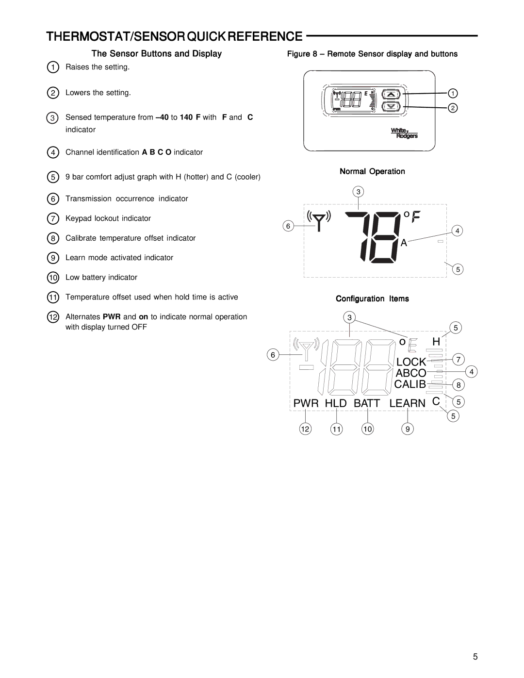
The Sensor Buttons and Display
1Raises the setting.
2Lowers the setting.
3Sensed temperature from
4Channel identification A B C O indicator
59 bar comfort adjust graph with H (hotter) and C (cooler)
6Transmission occurrence indicator
7Keypad lockout indicator
8Calibrate temperature offset indicator
9Learn mode activated indicator
10Low battery indicator
11Temperature offset used when hold time is active
12Alternates PWR and on to indicate normal operation with display turned OFF
Figure 8 – Remote Sensor display and buttons
1
2
Normal Operation
3
![]()
![]()
![]()
![]()
![]()
![]() o
o ![]()
![]()
![]()
6
4
![]()
![]()
![]() A
A
5
Configuration Items
3
5
![]()
![]()
![]()
![]()
![]()
![]() o
o ![]()
![]() H
H ![]()
6
![]()
![]()
![]() LOCK
LOCK![]() 7
7
![]()
![]()
![]()
![]()
![]()
![]() ABCO
ABCO![]() 4
4
CALIB![]() 8
8
![]() PWR HLD BATT LEARN C
PWR HLD BATT LEARN C ![]() 5
5
5
12 | 11 | 10 | 9 |
5
