Features
Miter Cutting Head
The miter cutting head is the unit that cuts the material and consists of a cast iron base, blade support unit and guard, transmission unit, and motor. The depth of cut is set by adjusting the depth cut stop. The miter cutting head swivels and locks into
Miter Position Lock
The miter position lock secures the miter cutting head from movement. The miter is secured when the lock is pushed all the way to the left and can be positioned when the lock is moved to the right.
Self-centering Vise
The
FK350 Controls
The control panel consists of the Power (On/Off) switch and High/Stop/Low switch, and an integral coolant system. To operate the machine, the Power switch must be set to on and the High/Stop/Low switch must be set for Hi or Low. Then depress the trigger handle to start.
FK350-SX Controls
This machine features a
Trigger Handle
The trigger handle (Figure 1) is located on the operating lever used to raise and lower the saw. It contains a
Figure 1
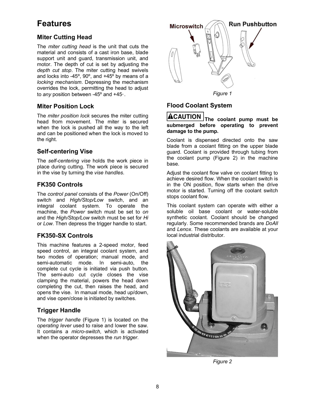
Flood Coolant System
![]() The coolant pump must be submerged before operating to prevent damage to the pump.
The coolant pump must be submerged before operating to prevent damage to the pump.
Coolant is dispensed directed onto the saw blade from a coolant fitting on the upper blade guard. Coolant is provided through tubing from the coolant pump (Figure 2) in the machine base.
Adjust the coolant flow valve on coolant fitting to achieve desired flow. When the coolant switch is in the ON position, flow starts when the drive motor is started. Turning off the coolant switch stops coolant flow.
This coolant system can operate with either a soluble oil base coolant or
Figure 2
8