8 | 9 | 4 | 5 | 6 |
7
1
3
![]() 10
10
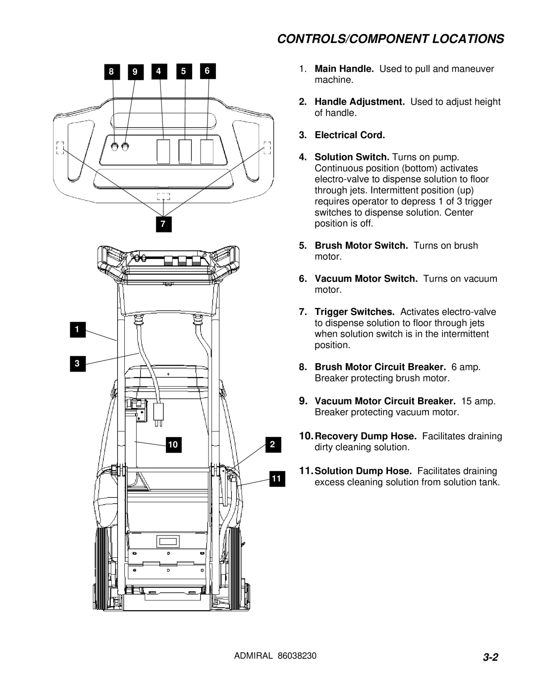
CONTROLS/COMPONENT LOCATIONS
1.Main Handle. Used to pull and maneuver machine.
2.Handle Adjustment. Used to adjust height of handle.
3.Electrical Cord.
4.Solution Switch. Turns on pump. Continuous position (bottom) activates
5.Brush Motor Switch. Turns on brush motor.
6.Vacuum Motor Switch. Turns on vacuum motor.
7.Trigger Switches. Activates
8.Brush Motor Circuit Breaker. 6 amp. Breaker protecting brush motor.
9.Vacuum Motor Circuit Breaker. 15 amp. Breaker protecting vacuum motor.
10.Recovery Dump Hose. Facilitates draining
2dirty cleaning solution.
|
| 11.Solution Dump Hose. Facilitates draining | |
| 11 | ||
| excess cleaning solution from solution tank. | ||
|
|
|
|
|
|
|
|
ADMIRAL 86038230 |