3.7 Route and connect the coax and wires
Determine the best location for the
Using a 7/16" wrench, attach the
Fig 3.7
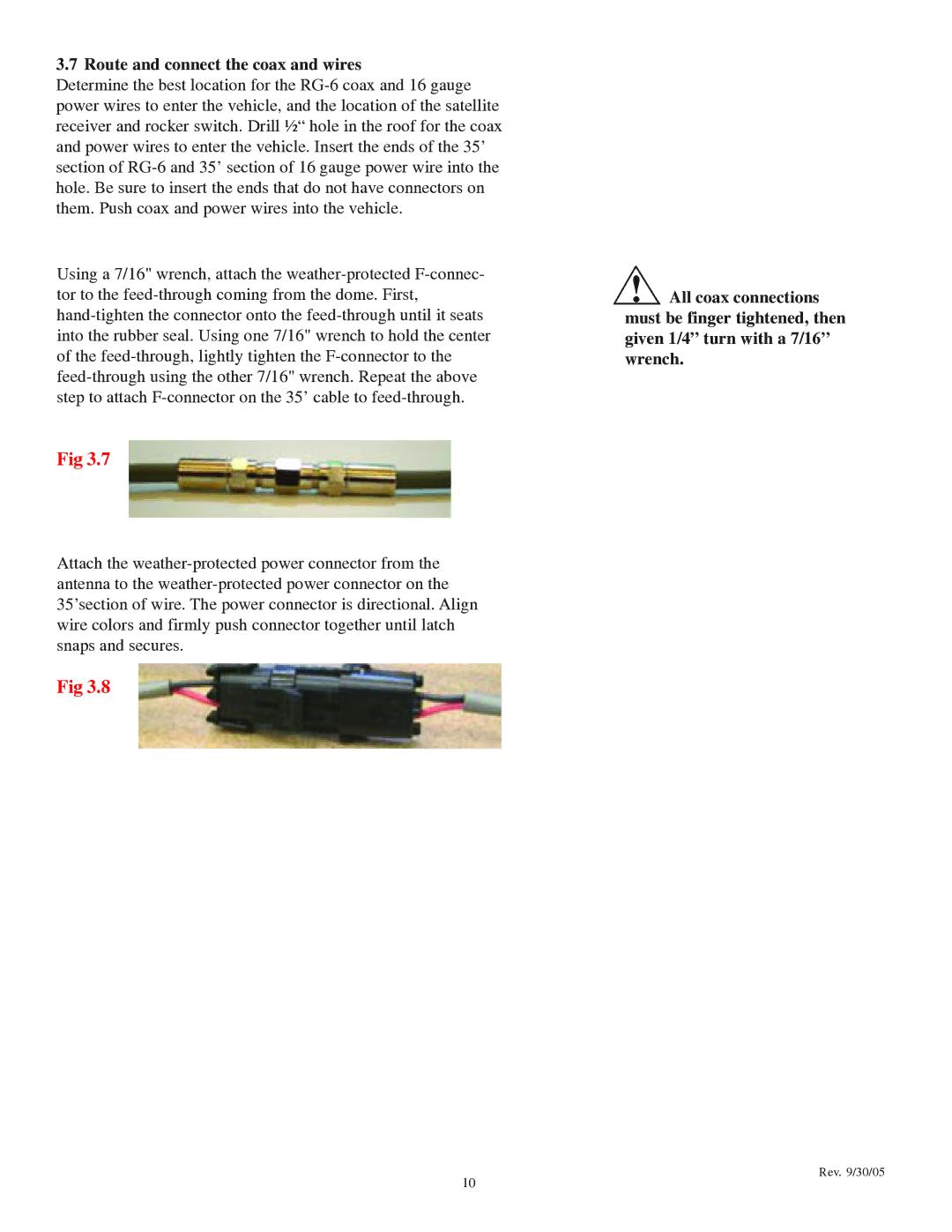
Attach the
Fig 3.8
![]() All coax connections must be finger tightened, then given 1/4” turn with a 7/16” wrench.
All coax connections must be finger tightened, then given 1/4” turn with a 7/16” wrench.
10
Rev. 9/30/05
Determine the best location for the
Using a 7/16" wrench, attach the
Fig 3.7
Attach the
Fig 3.8
![]() All coax connections must be finger tightened, then given 1/4” turn with a 7/16” wrench.
All coax connections must be finger tightened, then given 1/4” turn with a 7/16” wrench.
10
Rev. 9/30/05