3.5Mounting the Antenna Hardware Kit:
1. | Cable ties | 2 |
|
|
| |
2. | Rocker switch | 1 |
|
| 1. | |
3. | Surface mount box screw, #6 x 1/2 | 2 |
| 11. | 10. | |
4. | Wallplate, surface mount screw | 2 |
| |||
|
| |||||
5. | Surface mount screw, #6 x 3/4, white | 2 |
|
|
| |
6. | 2 |
|
|
| ||
7. | Small red flag connector | 2 |
|
|
| |
8. | Large red flag connector | 1 |
|
|
| |
9. | Cable clamps | 2 |
| 3. | 13. | |
10. | Surface mount box | 1 | 14. | |||
| ||||||
11. | Cable entry plate | 1 |
| 5. | 4. | |
12. | Wallplate, white | 1 |
| |||
|
|
| ||||
13. | Packaged screws | 30 |
|
| 12. | |
14. | Protective radome wipe | 1 |
|
| ||
|
|
| ||||
|
|
|
|
| 6. |
7.
Hardware Kit Contents | 8. |
|
|
| |
| 9. | 2. |
|
|
Level the vehicle before mounting antenna.
Clean the roof area that was selected in Section 3.4. Move the antenna unit to the roof and place in permanent location.
![]() When moving the antenna, always leave radome on to avoid damaging the antenna. Never handle the antenna unit by the cable or wiring.
When moving the antenna, always leave radome on to avoid damaging the antenna. Never handle the antenna unit by the cable or wiring.
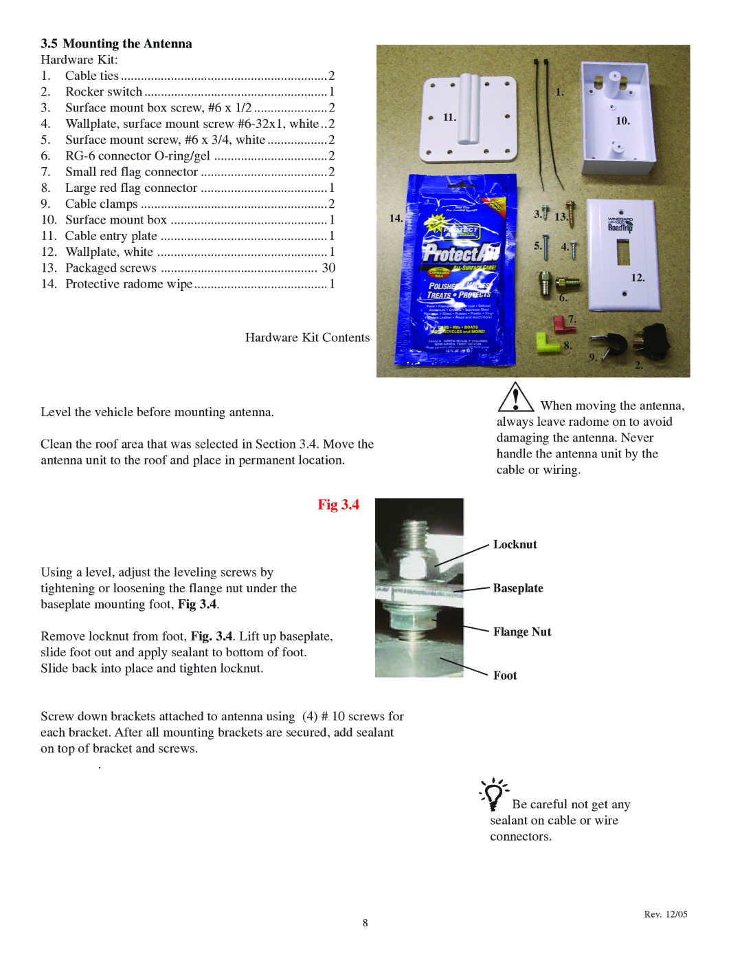
Fig 3.4
Using a level, adjust the leveling screws by tightening or loosening the flange nut under the baseplate mounting foot, Fig 3.4.
Remove locknut from foot, Fig. 3.4. Lift up baseplate, slide foot out and apply sealant to bottom of foot. Slide back into place and tighten locknut.
Screw down brackets attached to antenna using (4) # 10 screws for each bracket. After all mounting brackets are secured, add sealant on top of bracket and screws.
.
Locknut
Baseplate
Flange Nut
Foot
![]() Be careful not get any sealant on cable or wire connectors.
Be careful not get any sealant on cable or wire connectors.
8
Rev. 12/05